The Endian question – binary communication between Nextion and Arduino
Over the last months, we have seen a huge progress in the Nextion Mega IO project. Time for a little break to answer recurring readers’ questions. Today, we’ll talk about data formats in binary communication. An important point as soon as we leave the default ASCII command communication using the Nextion instruction set.
For the Nextion Mega IO project, we introduced a much more compact binary protocol, first to gain on transmission speed, second to showcase the Nextion’s “protocol reparse” mode, and third because it’s fun to explore new paths 😉 .
Our goal for today is to understand a bit of theory which will allow us to rework somewhat the Nextion Mega IO code in the future to make it simpler, easier maintainable and readable, and still more flexible. Then, adding the control over the up to 32 GPIO pins which we still have to implement, will be very easy. And later, when it comes to high speed communication between Arduino and Nextion for a CAN bus project (spoiler!), we will be thankful for all this preliminary work!
The binary protocol…
is described in detail here: The Nextion MEGA IO project – Part 1 – Nextion. Remember, we are always transmitting just 2 bytes for a read command and 3 bytes for a write command.
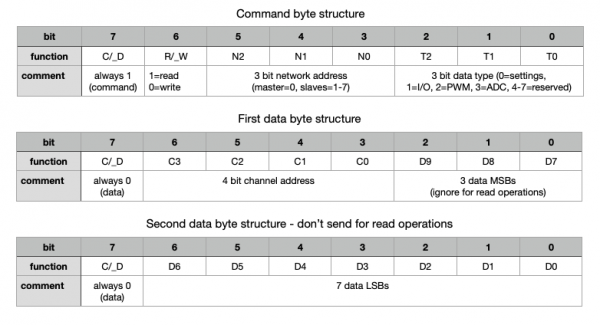
The first byte, which we called the command byte has its most significant bit 7 always set to 1, so that we may see that a new command sequence (or frame, if you prefer) begins. For all following bytes of the same frame (the data bytes), bit7 is always 0. Thats exactly how the Midi protocol does its framing, too. Bit6 of the command byte indicates if it’s a read command when set to 1 (which means that only 1 data byte will follow), or a write command when set to 0 which means that 2 data bytes will follow. Thus, with only the first two bits, we know exactly what to expect afterwards. The next 3 bits, bit5 to bit3 are the address bytes reserved for future use when we’ll extend the project to several Arduino Megas controlled by a single Nextion HMI. The speed factor is that after receiving the first 5 bits, the Arduino knows already if the whole sequence is addressed to it or if it can be resent immediately to the next in the chain. Huge Thanks to the HP engineers who created the HP-IL protocol around 1980, very inspiring! Finally, the last 3 bits, bit2 to bit0 give us the info which subsystem is addressed, settings, PWM, ADC, GPIO, Servo, or, or, or…
The second byte has bit7 set to 0 as seen above because it is not the command byte. Bit6 to bit3 indicate which channel within the addressed subsystem is addressed. Bit2 to bit0 are already the 3 most significant data bits when data is written. For read commands, these are ignored because data will only be transmitted in the answer to the read command, which is a write command.
If we have a write command, there will be a third byte, the second data byte. Its bit7 will be 0 again, and bit6 to bit0 hold the remaining 7 data bits of the overall 10bit data which can be sent.
Here again the graphic representation which is perhaps easier to read or to understand:
Now, how to code such byte sequences ?
Let’s take an example: After moving a slider on the screen to 255, its maximum value for PWM, the corresponding write command for that PWM channel, let’s say channel 3 which is pin5 on the Mega, shall be sent out from the Nextion.
First step is assembling the command byte: bit7 must be 1, bit6 = 0 write, bit5 to bit3 = 000, bit2 to bit 0 = 010 (binary “2” for PWM). Makes 10000010b in binary or 0x82 in hexadecimal.
Data byte 1 starts with 0, then there is 0011 (binary “3” for the channel) , and 001 because the data which shall be sent is 255 or 11111111b. The remaining seven “1” go into the second data byte whose d7 is 0 again. Thus Data1 = 00011001b or 0x19 hex, and Data2 = 01111111b or 0x7F hex.
That means that now, since we have 3 hex values, we could use
printh 82 19 7Fwhich works great, as long as we’d be sending always the same data to the same channel of the same subsystem. But, to stay with the PWM example, there are 12 different channels which can take 256 values each. Thus, we need a way to generate the corresponding write command in code. For example using a 32bit (or 4 byte) integer assembled with logical operations, and then sending 3 of its 4 bytes out with the prints command. Let’s give it a try before we move on:
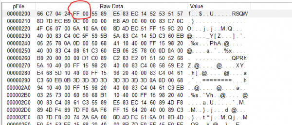
prints 0x0082197F,3This does not work. Let’s get out our logic analyser and see what the Nextion does send out: 7F 19 82 which is definitively NOT what we want. Oh surprise, the byte order is reversed
The Endian problem
As soon as computers or microprocessors learned tu handle more than 1 single byte at a time, which was when 16bit and 32bit CPUs came to market, there was the question of how to organise such longer words in the (still bytewise organized) memory. The most significant byte first (so called Big Endian) or the least significant byte first (Little Endian). Different CPU manufacturers decided for different approaches, there was no standardisation. Which makes that still nowadays, even if the compilers make this transparent for us, we hurt occasionally this problem, for example using the prints command on the embedded Arm Cortex M0 MCU of our Nextion screens. From which we conclude that the Arm Cortex M architecture is Little Endian. Or not?
Studying the Arm Cortex-M handbook, we see that in theory, this architecture can handle both, little and big endian. It’s up to the manufacturer to decide which one to take when producing the processors. Thus, it’s ST Micro who decided to go for little endian.
The solution and its advantages
The solution is easy. The command byte has always to be the least significant byte of a longer word. The advantage is that it can easily be built from constants. since it remains always in the same rightmost place. We only need to shift the channel address (for read and write) and data (for write only) towards the left. Proceeding this way, we’ll build our command sequence in reverse order, so that at the end, we had
prints 0x007F1982,3which sends the bytes out in the expected order: 82 19 7F.
We’ll see next time in detail how to simplify the command sequence generation using constants and logical operators, and thus making our code on both sides, Nextion and Arduino simpler, better readable, and better maintainable.
Last, but not least
You have any questions, comments, critics, or suggestions? Just send me an email to thierry (at) itead (dot) cc! 🙂
And, by the way, if you like and you find useful what I write, and you are about to order Nextion stuff with Itead, please do so by clicking THIS REFERRAL LINK! To you, it won’t forcibly make a change for your order but on some products, you may even get a 10% discount using the coupon code THIERRYFRSONOFF. In ever case, it will pay me perhaps the one or the other beer or coffee. And that will motivate me to write still more interesting blogs 😉


