Control Servo motors with Nextion HMI – Part 1
Introduction
Over the last weeks, I got several mails from readers asking about the use of servo motors (or short, servos) together with Nextion HMI. The ones wanted to control a few servos directly from the Nextion’s (Enhanced and Intelligent series) GPIO, others suggested to extend the Nextion Mega I/O project to allow controlling servos. The scientific approach is to gather information before taking a decision or even starting a development, thus, let’s look at how servos work and how they are controlled, first. And then, let’s see how the Nextion HMI can be used for that.
What is a servo and how does it work?
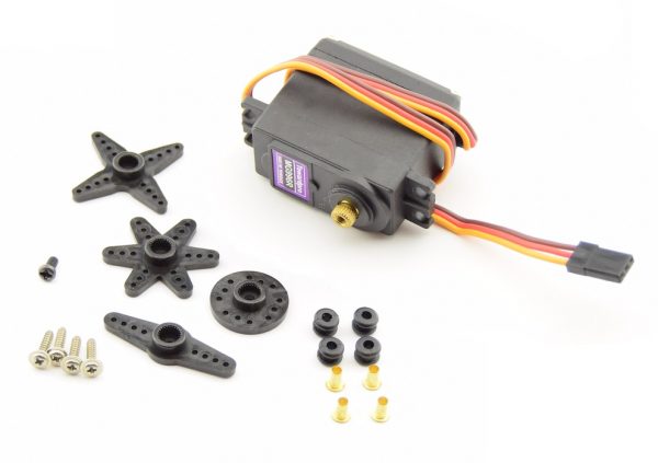
A servo is a small motor, packed in a housing together with a gearbox, trading rotation speed against force, and a potentiometer to give feedback about the current position of the actuator. We do not need to tell the motor to turn, how many turns, and in which direction, we just tell the servo in which position we want to see the actuator. The internal electronics will then decide in which direction the motor will have to turn and automatically stop it when the desired position is reached.
One common mistake to avoid
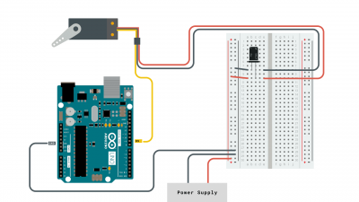
When quickly testing a few things on the bench with Dupont wires, one tends to forget that servos have motors and that motors draw a lot of current from the power supply. Common servos have rated currents from 1.5A to 2.5A. That means that they can not be powered from the Arduino’s +5V and GND pins, especially when the Arduino is powered from an USB port – an extra separate 5V power supply is always required to source the required currents. Since not all servos will probably be active at the same time and the maximum current is only required when the motor starts, counting 1.5A per servo is a good rule of thumb. Do not forget to connect the extra power supply’s GND to the Arduino’s GND, though, so that there is a common GND potential for the control signal. It is also good practice to add a 100uF capacitor between each servo’s +5V and GND wires, the closest possible to the servo to smoothen current peaks.
How is a servo controlled?
As you can see on the picture above, three wires, a brown or black one for GND, a red one for +5V, and an orange or yellow one for control are enough. On earlier analog servos, one would apply a control voltage between 0V and 5V to the control wire, going from 0V for a 0° position to 5V for a 180° position. An internal voltage comparator would simply drive the motor until the voltage across the internal potentiometer was equal to the control voltage and things were literally settled.
But when people started using servos in RC cars, aircraft, boats, etc., transmitting an analog control voltage error-free without interference and noise over a RF channel was not possible. And if the signal was temporarily cut, the servo would immediately fall back to the 0° position with sometimes fatal consequences. People had to find a way to transmit the desired position in a more robust way. And that was done (since more elaborated digital technologies weren’t yet affordable at that time) with a special version of PWM.
The PWM frequency is fixed at 50Hz, so that a single transmission takes always 20ms. The pulse length (the HIGH time) is usually minimal 1ms for 0° and maximal 2ms for 180°, then followed by a 18 to 19ms pause (the LOW time). Some servos have extended timing ranges – if there is a doubt, look at its data sheet. Pulses shorter than the minimum time are ignored to filter out parasitics and interferences. The same applies to everything which falls into the LOW time: it’s simply ignored. All that reduces greatly transmission errors. And the servo does not move without receiving a pulse with a valid length which means that if the transmission is interrupted for some reason, it will remain in the last position.

The first analysis and conclusion
Now, let’s imagine how we could drive such a servo with the Nextion’s GPIO. We’d set the PWM frequency to 50Hz with pwmf=50 to obtain the 20ms PWM period. As the system variables pwm4 to pwm7 can take values from 0 to 100, that means that we are handling 20ms/100 = 0.2ms steps. Thus, the pwm4 value to set for 1ms would be 5, and for 2ms, it would be 10. The intermediate values 6, 7, 8, and 9 would then correspond to 36°, 72°, 108°, and 144° – a very coarse and rather clumsy control…
Conclusion: Driving a servo directly from a Nextion HMI is not possible.
In that case, let’s use an Arduino
Yes. Simply because there is a mature and well known working Servo library available. All we’ll have to do is interfacing our Nextion Mega I/O project with Servo.h and to slightly extend our hyper efficient protocol. But that’s stuff for next Sunday…
Last, but not least
You have any questions, comments, critics, or suggestions? Just send me an email to thierry (at) itead (dot) cc! 🙂
And, by the way, if you like and you find useful what I write, and you are about to order Nextion stuff with Itead, please do so by clicking THIS REFERRAL LINK! To you, it won’t make a change for your order. But it will pay me perhaps the one or the other beer or coffee. And that will motivate me to write still more interesting blogs 😉


