The Sunday Blog: Graphic programming
The fully functional and animated artificial horizon
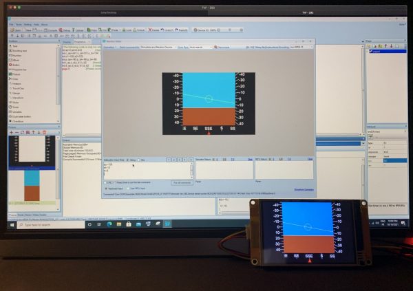
After we saw in last week’s Sunday Blog all the basics of artificial horizons and made a quick proof of concept simulating a gyroscope with 2 sliders, here is now the fully functional version which can be remote controlled by an Arduino or any other MCU connected to a gyroscope module!
But before we look into coding details, I’ll make a short description of the used GUI techniques to achieve an excellent and animated performance:
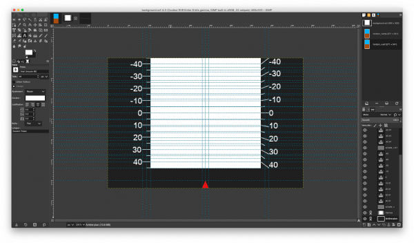
The static background picture
To save memory and drawing/refresh cycles at runtime, everything which doesn’t move, the graduations on the left (elevation angle), on the right (tilt angle), and the red triangle at the bottom for the azimuth/compass are all part of a 480x320px bmp which is created beforehand in a bitmap graphics program. Many people use Photoshop for that, I prefer the free, open source alternative: The Gimp. The proceeding is more or less the same, you fiddle with guide lines (have your scientific calculator at hand for a pixel perfect layout), layers which allow creating sub-parts of the picture and position these where needed, paths which allow you to trace perfect lines between two points which snap on the intersection of two guide lines, and text elements, again placed with the help of guide lines at pre-calculated positions.
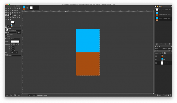
Virtually moving pictures
We’ll have to create two of these: One to fill later the huge white square in the middle with the upper sky and lower ground part. Since we need to show whatever representation of an elevation angle between +45° (only sky) and -45° (only ground), we create a picture with the double height and we’ll use the xpic command later to crop the square which corresponds to our current elevation angle from this rectangle.
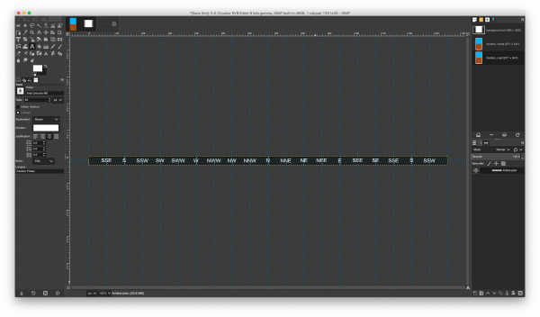
The second one is for the sliding azimuth/compass graduation. Here, we need the full round (-180° to +180°) plus a little extra, so that we don’t get an error at full South in the center when the cropping reaches the borders:
A line for the tilt angle
As I explained last week, the Nextion’s internal MCU is not a GPU, capable to rotate a 271x271px picture. Thus, we could create 91 of these elevation rectangles like above, each with a different tilt angle from -45° to +45°, but hey, 26.7MB as bmp (ok, a little less on the Discovery series due to its improved picture compression) is ways too heavy for our small 3.5″ HMI displays. Thus, we go for the solution used by old analog artificial horizons: we use a simple yellow line, drawn with the line GUI drawing command. And just as an eye candy, we add a small circle with the cir command.
Lights, camera, action: the animation
Imagine your MCU sends “el=25ÿÿÿ” to the Nextion HMI and then, a few seconds later “el=-30ÿÿÿ”. Our screen would jump around which is not very realistic. Thus, the main timer tm0 will take care of transforming jumps into natural and fluid movements with 20fps.
Demo mode
A dual state button in the bottom right corner enables or disables the demo timer tm1 which changes the scenery every 2.8 seconds by setting new values to the az, el, and ti variables. This allows you to seethe smooth transition from one scenery to the next. If you want to use this project in a real life application, just delete the button bt0 and the timer tm1 from the project file.
And now to the GUI code
First, we need to declare some variables: az, el, and ti for the azimuth, elevation, and tilt angle input. These can be modified at runtime either from Nextion code like in the Demo mode, or from “outside”, which means from your MCU which has a gyroscope module connected over I2C. Technically, this makes no difference. Then we need a few constants for drawing, the center values c_az, c_el, c_ti, and the right and left border x coordinates for our tilt line, x1 and x2. Since we want to save CPU cycles and only re-calculate everything when an input angle has changed, we need variables to keep the previous values p_az, p_el, and p_ti for comparison. These are preset to absurd values, so that there will be already a redraw with default values be triggered at the first timer run, before the Demo mode or the MCU send “real” angles. Then, in case an angle input has changed, the new target coordinates t_az, t_el, t_ti1, and t_ti2 for the following drawing routine are calculated. The drawing coordinates d_az, d_el, d_ti1, and d_ti2 are then incremented or decremented in small steps on each timer event for a fluid animation. Afterwards, there is still animation_count for the consecutive sceneries in demo mode, and we set baud to 115200 for the communication with the MCU before the page 0 is loaded:
//The following code is only run once when power on, and is generally used for global variable definition and power on initialization data
int az=0,el=0,ti=0                   //input variables
int c_az=541,c_el=137,c_ti=134   //center values
int x1=105,x2=375
int p_az=-90,p_el=-90,p_ti=-90       //previous variables
int t_az,t_el,t_ti1,t_ti2         //transformed input variables
int d_az,d_el,d_ti1,d_ti2      // drawing variables
int anim_count=0                    // for demo mode
baud=115200
page 0                       //Power on start page 0
In the postInitialize event of page 0, the drawing variables are preset to the default (center) values and the timer 0 is then enabled to check for changes and to update and animate everything.
d_az=c_az
d_el=c_el
d_ti1=c_ti
d_ti2=c_ti
tm0.en=1
All the magic sauce is in the event code of timer 0. First, there is a check for each of the three input variables for changes. Then, these are “sanitized” which means that the azimuth is brought to the range from -180° to 180° by adding or subtracting 360° if needed, and elevation and tilt are hard limited to the range from -45° to +45°. Afterwards, the new target values for drawing are calculated.
In a second step, the animation comes into play. The drawing coordinates are compared to the target coordinates and then increased or decreased by a small amount (all the GUI design is made that 3px correspond to 1°) before everything is (re-)drawn until the drawing coordinates match the target coordinates:
// check if azimuth has changed
if(az!=p_az)
{
  p_az=az
  // sanitize:
  while(az>180)
  {
    az-=360
  }
  while(az<=-180)
  {
    az+=360
  }
  // transform:
  t_az=3*az+c_az
}
// check if elevation has changed
if(el!=p_el)
{
  p_el=el
  // sanitize:
  if(el>45)
  {
    el=45
  }
  if(el<-45)
  {
    el=-45
  }
  // transform:
  t_el=-3*el+c_el
}
// check if tilt has changed
if(ti!=p_ti)
{
  p_ti=ti
  // sanitize:
  if(ti>45)
  {
    ti=45
  }
  if(ti<-45)
  {
    ti=-45
  }
  // transform:
  t_ti1=-3*ti+c_ti
  t_ti2=3*ti+c_ti
}
// now move:
if(d_az<t_az)
{
  d_az+=3
}
if(d_az>t_az)
{
  d_az-=3
}
if(d_el<t_el)
{
  d_el+=3
}
if(d_el>t_el)
{
  d_el-=3
}
if(d_ti1<t_ti1)
{
  d_ti1+=3
}
if(d_ti1>t_ti1)
{
  d_ti1-=3
}
if(d_ti2<t_ti2)
{
  d_ti2+=3
}
if(d_ti2>t_ti2)
{
  d_ti2-=3
}
// and finally draw:
xpic x1,272,271,30,d_az,0,2
xpic x1,0,271,271,0,d_el,1
line x1,d_ti1,x2,d_ti2,YELLOW
cir 240,c_ti,18,YELLOW
doevents
And that’s it! The demo mode code is rather trivial, you’ll immediately see how it works when you look at it (hint: TouchPress event of bt0 and Timer event of tm1) after opening the hmi file (download below) in the Nextion editor.
Coding on the Arduino (or other MCU) side
Since there are many different MCUs and development environments, many different gyroscope modules and libraries, I’ll just give the general strategic flow as symbolic code:
- Include the library which corresponds to your gyroscope module
- In setup(), initialize the I2C communication with the gyroscope, then call the calibration routines
- In loop(), check if new data from the gyroscope is available and read it into the corresponding variables
- Still in loop(), compare the obtained values to the previously sent ones (requires a 2nd set of variables to compare)
- Still in loop(), if one or more angles have changed, send these to the Nextion HMI over serial
- Still in loop, update the previously sent variables with the current ones.
Sending angles to the Nextion is as easy as sending “az=” for azimuth, “el=” for elevation, or “ti=” for tilt, followed by the corresponding integer value and the terminator (3 x 0xFF).
Here is the project file to download: horizon3.hmi. It can be compiled and uploaded to whatever Nextion 3.5″ HMI. It runs on Standard, Discovery, and Enhanced series without problems. Or you can simply play with it in the debugger/simulator.
Question? Critics? Suggestions? Write in the Nextion forums (registration required).
Happy nextioning!


