The Sunday Blog: Graphic programming
Dashboard with artificial horizon on Nextion HMI part 1
Reading through different Nextion HMI related forums, discussion groups, and Facebook pages, I see more and more people using Nextion HMIs in or as dashboards for (real or simulated) cars of all sizes, bikes, boats and even small airplanes. Especially for the two latter, a so-called artificial horizon might be of interest. Thus, I decided to start a short series, showing a few programming techniques which can help with this.
Angles, angles and angles
In a 3-dimensional space, three angles are of interest. These are called azimuth, elevation, and tilt. The first both define your movement vector, that’s the direction in which you move.
Imagine standing upright, turned towards North and looking straight in front of you. Now, you azimuth is 0°. Now, turn you head towards your right side and your azimuth will increase until it reaches 90° when you look towards East over your right shoulder. Turning towards your left side in the same way will decrease your azimuth until reaching -90° (or 270° since everything is modulo 360) when you look towards West. Making a full half turn to either side makes you look towards South will change your azimuth to + (or -) 180°. In simple words, the azimuth angle is your moving direction on a flat horizontal map. Whatever horizon we see will scroll laterally.
Up to now, we were always looking or moving on a horizontal level, but what if we look or move upwards or downwards like an airplane increasing or reducing its height over ground? Thats where the elevation angle comes into play: When we look or move straight forward, the elevation angle is 0°. Lifting our head to look upwards increases the elevation angle until it reaches its maximum at 90° which happens when we look at a point straight above us. On the other side, looking downwards decreases the elevation angle until it is at its minimum of -90° when we look at our feet or below. A horizon would move down and up, accordingly.
Finally, we can tilt our head to simulate a rotation of the horizon, which corresponds to the inclination when a motorbike or an airplane makes a turn, or when waves toss a boat right and left. This “tilting” can also be measured, and is characterized by – as its name indicates – by the tilt angle.
And how to display everything?
First of all, we need a sensor to capture these angles. These are called gyroscope and there is a bunch of these on the market, on of the most prominent being the GY-521 module which communicates well with any Arduino or other MCU board over I2C and is well supported by a bunch of libraries. From which we understand that we’ll need an external processor since the Nextion’s integrated MCU does neither speak “I2C” nor can it do the required calibration and coordinate transformation which are integrated functions of most of the available libraries.
Let’s imagine that our Arduino is well programmed, connected to the gyroscope module, and does now send our three angles to the Nextion HMI. The simplest way, on HMI side, would be to display the three angles as numbers. While such a solution is technically correct, it is far from being ergonomic! In an ideal world, we were assisted on our ride by a front camera and a screen which adds some numeric details (or graduations, or a grid) to the picture. But this is still a very computation intensive and expensive solution, even nowadays.
That’s why engineers invented techniques around a simplified and abstract picture and they called it the “artificial horizon”.
What does an artificial horizon look like ?
The simplest variant is a flat line, just like any horizon. That’s how they started, using cathode tube screens, similar to an oscilloscope screen. The x and y deflection of this tube screen allowed to move the line up and down to visualize the elevation angle, and to tilt the line to visualize – you guess it – the tilt angle. Since the horizon line was flat, there were no means to visualize the azimuth angle. Thus they added a second line from the center of the screen towards its border, indicating North like on a compass.
Later, when color screens came up, things became somewhat more ergonomic and realistic. The upper part of the picture became blue like the sky and the lower part brownish like the earth. But there wasn’t yet the needed calculation power to turn the whole picture because this requires a 2D coordinate transformation with sin() and cos() functions of each pixel of the picture. Thus, the tilt angle continued to be visualized by a line which was much easier to calculate, even when tilted.
While expensive systems today work with numeric and graphic coprocessors to make the artificial horizon as realistic a possible, with rotation, variable graduations, and more numeric information in half-shadowed overlays, this is beyond the hobbyist’s scope. For the moment, we’d like to use a Standard, Discovery, or Enhanced series Nextion HMI. Thus, we’ll do without coordinate transformation, without rotation, and without transparency. But we’ll make some unorthodox use of GUI drawing functions… 😉
A first, yet incomplete demo project
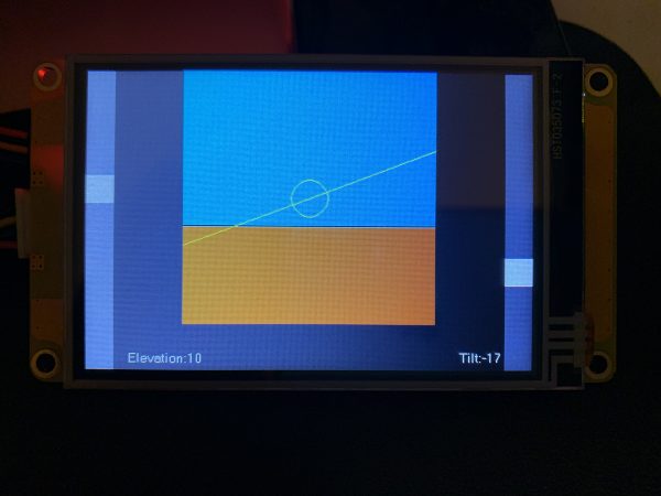
Designed for a 3.5″ screen, this project might be compiled for all variants, Standard, Discovery, or Enhanced. As you can see in the picture above, two sliders at the right and the left of the screen all to set the elevation and tilt angles manually. This saves you for the moment from adding an Arduino and a gyroscope module. You may compile and upload it to whatever 3.5″ Nextion, or simply load it in the Simulator/Debugger and play with it. The code is (still) extremely simple and should be self-explaining. But I’ll comment on a few details in the next part of this article series.
Initially, I had planned to use a blue background and to draw a brown rectangle on it, with the starting y-coordinate depending on the elevation angle. But I found that solution was not optimal, especially when the brown part would move downwards, which would require e refresh/redraw of the blue background before. Thus, I decided to use a simple bitmap picture with the double height of the drawing window, blue in the upper half and brown in the lower half. Then, with the xpic command, the required square (depending on the elevation angle) is cut out and copied to the screen which is quicker and more fluid, at least on the Discovery series.
Here it is: horizon1.hmi
Have fun playing with this first approach. We’ll extend and refine it very soon. Stay tuned!
Happy nextionning!


