The Nextion Mega I/O Project – Part 5
Please read before:
The Nextion MEGA IO project – Part 1 – Nextion – The Nextion MEGA IO project – Part 2 – Nextion – The Nextion MEGA IO project – Part 3 – Nextion – The Nextion Mega I/O project – Part 4 – Nextion
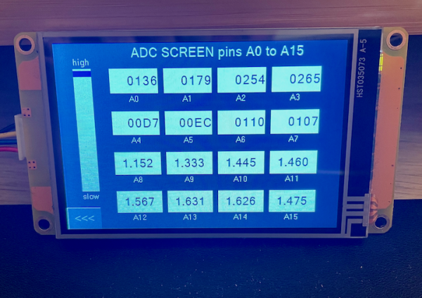
Reading analog inputs – 16 at once !
I must admit that I was surprised by myself. After I made the required extension to the Arduino Mega code and after I designed the ADC screen as in the picture above and added the code, it worked immediately and it was much more fluid than I had thought before… This is for sure due to the extremely compact protocol which requires that per channel, only 2 bytes are sent from the Nextion to the Arduino as a read request and only 3 bytes are required from the Arduino the the Nextion to send the requested data back. Even with 16 channels on the screen, there are only 80 bytes transmitted for a full screen refresh – 32 in one direction and 48 in the other. At 115200 baud and including start and stop bits, the full data exchange is done in less than 7ms which is the worst case. The limiting factor is the Arduino’s ADC hardware which has to do the 16 channel multiplexing and the 16 A/D conversions.
This allowed me to add a slider to the screen which allows to adjust the refresh interval in 250ms steps between 500ms and 5s. It controls the .Tim attribute one of the two timers on that page, the one called caller. Its code is very simple, it does just temporarily disable the listener to prevent conflicts, send out 16 x 2 byte read requests for all channels and finally re-enable the listener:
// read request for all 16 channels from the Arduino Mega
listener.en=0
printh C3 00
printh C3 08
printh C3 10
printh C3 18
printh C3 20
printh C3 28
printh C3 30
printh C3 38
printh C3 40
printh C3 48
printh C3 50
printh C3 58
printh C3 60
printh C3 68
printh C3 70
printh C3 78
listener.en=1
All these bytes could theoretically stand in one line behind a single printh command, but I thought that this way, it was easier to read and people could simply comment out a few lines if less that the full 16 channels were required.
The other timer is the already well known listener which processes the data which the Arduino sends back. It is quite similar to the one on the PWM pages. It just filters for a different data type (ADC instead of PWM) and it handles 10 data bits (values from 0 to 1023) instead of the 8 which are used for PWM (values from 0 to 255). Since this was almost only copy ‘n paste, I decided to add some extra luxury – the ability to display the data in different formats without modifying the code!
If you look at the picture above or if you load the demo project at the end of this article), you’ll see number components in the first two rows. I set the .format attribute to Decimal for the first row and to Hex for the second row. Feel free to modify this to taste. In ever case, the raw ADC value (from 0 to 1023 decimal or from 0 to 03FF hex) will displayed. In the third and fourth row, I placed float components with 3 decimals. If the listener code detects that you put a float component instead of a number component, it will see the different object type and convert the raw data into a value from 0.000 to 5.000 V. The only thing to take care of – because of the indirect addressing – is that the object ids of the associated components on the page have to remain the same: id 1 for channel 0, id2 for channel 1, and so on until id 16 for channel 15.
Here the listener event code, changes compared to the already PWM version in bold:
// Check if something has arrived in the buffer
while(usize>2)
{
  // Check if the first byte in the command buffer is a command byte, if not, discard it
  if(u[0]<128)
  {
    udelete 1
  }else
  {
    // Check if there seems to be a valid write command in the buffer and process it
    if(usize>=3&&u[1]<128&&u[2]<128)
    {
      // Check if it is for this page (write ADC)
      if(u[0]==0x83)
      {
        channel=u[1]>>3&0x0F
        data=u[1]&0x07<<7|u[2]
        if(b[channel+1].type==59)
        {
          // if the component is float, convert to voltage from 0 to 5V
          b[channel+1].val=data*5000+512>>10
        }else
        {
          // display the raw value
          b[channel+1].val=data
        }
      }
      // Discard the command
      udelete 3
    }else
    {
      // Delete the orphaned command byte
      udelete 1
    }
  }
}
No big changes, no rocket science !
Finally, there is the slider which on release sets the timer interval for the caller, which is a one liner:
caller.tim=-250*h0.val+5000
The Arduino side
The small .ino file has still not changed since it does only the object and communication initialization in setup() and checks periodically in loop() if new requests came in. Everything is handled inside the NexIO object which is an instance of the NexMegaIO class, defined in the NexMegaIO.h file.
It’s core function process() which analyzes incoming data and branches depending on if it’s a command or a data byte, if it’s a read or write command, and which extracts data type and channel information, required just a little extension for the “new” data type 3 (ADC):
...
            switch (_type) {
              case 0x02:                      // PWM
                onUpstreamPWMread(_channel);  // call the specific handler
                break;
              case 0x03:                      // ADC
                onUpstreamADCread(_channel);  // call the specific handler
                break;
              default:  // do nothing
                break;
            }
...
Since there is a new function call onUpstreamADCread(_channel), we have naturally to define this new (private) function below:
...
    // Reply to a ADC read request from the Nextion
    void onUpstreamADCread(uint8_t channel) {
    uint16_t adcdata = analogRead(channel+54);
    uint16_t chndata = channel << 11 | (adcdata & 0x0380) << 1 | (adcdata & 0x7F);
    NexPort.write(0x83);  // Command byte for write ADC
    NexPort.write(highByte(chndata));
    NexPort.write(lowByte(chndata));
  }
...
Again, it’s short simple and compact which proves that if a project is well thought and systematically designed on an abstract level, beforehand, coding is quick and easy afterwards!
Please find the .hmi file for the Nextion here: mega_io_ext5.HMI
and the Arduino code (.ino file and our pseudo-library’s .h file) here: NexMegaIOdemo
Here still a short video to show how quick, smooth, and fluid everything runs:
Reader’s feedback
I got a kind email from a reader who asked if it was possible to control servos, especially analog feedback servos, from a Nextion HMI. The Nextion’s PWM capabilities (only available on Enhanced and Intelligent series) aren’t sufficient for precise servo control and protection against out-of-range timing. And no Nextion has analog inputs to read the servos’ position back from the additional feedback potentiometer. Thus, an external MCU as an “interface slave” with an approved servo library will be required to translate the Nextion’s “wishes” into precise servo pulses, to read the analog position back and to transmit it to the Nextion.
That looks like a perfect application for what we are actually doing with our Nextion Mega I/O project. Since today, we can already read analog values. And with a little extension and the introduction of a new data type for the 0 to 180° data to send to the servos (which will be a close variant of the PWM thing), we may see a servo page in this project, very soon. I’ve just to wait that the ordered servos arrive here in France…
For today, thanks for reading and happy Nextioning!
Questions, comments, critics, suggestions? Just send me an email to thierry (at) itead (dot) cc! 🙂
And, by the way, if you like what I write, and you are about to order Nextion stuff with Itead, please use my referral link! To you, it won’t make a change for your order. But it will pay me the one or the other beer or coffee. And that will motivate me to write still more interesting blogs 😉


