The Nextion Mega I/O project – Part 4
It’s big time that we move on with our Mega I/O project as promised!
After we discussed everything in theory and designed an efficient protocol for up to 8 “network” nodes in part1, made a strategy for optimized coding in part2, and had a first working demo in part3, other topics like new SONOFF hardware and the Black Friday sales had priority. But now, it seems like we might finally move on.
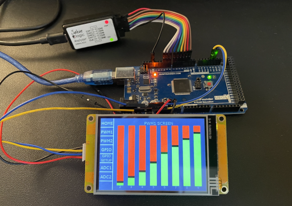
Our first demo allowed us already to control the 12 PWM channels of the Arduino Mega from two Nextion pages, PWM1 and PWM2. But as attentive readers gave feedback, there was still a huge flaw. After switching to a different HMI page and coming back, the PWM settings on the Arduino Mega persisted, but the Nextion showed everything reset to default value. This was the “throw and forget” mentality in the first demo version because there wasn’t yet a way to read back the settings from the Arduino to the Nextion.
Why read back? Could we not simply make the controls on the Nextion side global, so that the once set values would not get lost when changing pages? Yes, but… first, with so many controls – and much more to come since at the end, we want to control up to 7 daisy-chained Arduinos, we risk to saturate the precious RAM of the Discovery series HMI. And the Nextion risks to not to be aware when other code on the Arduino changes a setting. That’s why I’d consider that reading back the actual settings from the Arduino to the Nextion is the way to go, especially since we definitively need a read mechanism later, to display the current values from the ADC pins and the digital input pins.
Not much to do on the Arduino side – everything was already prepared
The Arduino code had already everything . The changes since last time in NexMegaIO.h are thus rather cosmetic, I restructured the code a little bit to make everything better readable and packed some stuff in extra functions to allow the object to evolve in an easier way in the future. You’ll find the download link as always at the end.
Issuing read requests from the Nextion to the Arduino
Our packed custom protocol being still very efficient, sending out 2 bytes is enough to ask the Arduino for the value of a specific PWM channel. It is enough to request the current values when a PWM page is loaded. Later changes will come either from the Nextion itself, so it will be automatically aware of these, or there will be settings changed by code running on the Arduino in which case it will have to write these not only to the pin, but to the Nextion, too. Thus, the Nextion will have to be listening permanently as we’ll see in the next paragraph.
Let’s look at the PWM pages’ Postinitialize Event code, first page PWM1:
// read request for all 8 channels from the Arduino Mega
listener.en=0
printh C2 00
printh C2 08
printh C2 10
printh C2 18
printh C2 20
printh C2 28
printh C2 30
printh C2 38
listener.en=1
First, the listener (see next paragraph) is temporarily disabled to avoid conflicts and 8 2-byte read commands are sent out. Basically, a single printh command, followed by all 16 bytes would have done the job, but I wanted to keep the code readable. Then, the listener is enabled again.
For the PWM2 page, things are pretty similar:
// read request for all 4 channels from the Arduino Mega
listener.en=0
printh C2 40
printh C2 48
printh C2 50
printh C2 58
listener.en=1
Listening to write requests coming from the Arduino
Since the Arduino will answer to our read requests with write requests in exactly the same form as the Nextion sends its write requests to the Arduino, decoding these is also done in a very similar way in Nextion programming language. The Nextion code is even somewhat simpler, because in opposite to the Arduino, on the Nextion, there is always only one page listening for a specific type of data (PWM or GPIO or ADC) and only for a limited number of channels which allows pre-filtering and then simplified decoding. The “Listener” is nothing other than a timer whose code is launched every 100ms. But before we do an in-depth look into what it does, we have to declare a few additional helper variables in the program.s tab and to switch the system variable recmod to 1, so that we can access the serial buffer directly and process the incoming bytes following our own rules. We comment out the famous startup sequence, so that the Arduino will not be troubled by other than our willingly sent bytes in our custom protocol.
Here program.s:
//The following code is only run once when power on, and is generally used for global variable definition and power on initialization data
int cmdbuf=0, temp=0
int menupage=0
int channel=0, data=0 // helper variables for decoding
baud=115200//Configure baudrate
dim=100//Configure backlight
recmod=1//Serial data parsing mode:0-Passive mode;1-Active mode
//printh 00 00 00 ff ff ff 88 ff ff ff//Output power on information to serial port
page 0                       //Power on start page 0
The “Listener”
As stated above, the listener is a timer to be placed on every page and with event code which checks the incoming data for errors, filters depending on the expected data type and channel range for the page, and finally decodes the write request and sets the corresponding control’s value. Everything is optimized for shortest runtime, so that later, we may run the timer even with much shorter intervals than 100ms, for example to track the analog input pins. That means that it will for example not wait for an incomplete command to fully arrive, it will leave the buffer “as is” and process it at the next run.
For the PWM1 page, the listener code is as follows :
// Check if something has arrived in the buffer
if(usize>0)
{
  // Check if the first byte in the command buffer is a command byte, if not, discard it
  if(u[0]<128)
  {
    udelete 1
  }else
  {
    // Check if there seems to be a valid write command in the buffer and process it
    if(usize>=3&&u[1]<128&&u[2]<128)
    {
      // Check if it is for this page (write PWM and channel bit C3 not set)
      if(u[0]==0x82&&u[1]<64)
      {
        channel=u[1]>>3&0x07
        data=u[1]&0x01<<7|u[2]
        b[channel+1].val=data
      }
      // Delete the processed command from the buffer
      udelete 3
    }else
    {
      // Delete the orphaned command byte
      udelete 1
    }
  }
}
And for the PWM2 page, it’s again pretty similar, with respect to the different channel numbers (the few changes in bold):
// Check if something has arrived in the buffer
if(usize>0)
{
  // Check if the first byte in the command buffer is a command byte, if not, discard it
  if(u[0]<128)
  {
    udelete 1
  }else
  {
    // Check if there seems to be a valid write command in the buffer and process it
    if(usize>=3&&u[1]<128&&u[2]<128)
    {
      // Check if it is for this page (write PWM and channel bit C3 set)
      if(u[0]==0x82&&u[1]>=64)
      {
        channel=u[1]>>3&0x03
        data=u[1]&0x01<<7|u[2]
        b[channel+1].val=data
      }
      // Discard the processed command
      udelete 3
    }else
    {
      // Delete the orphaned command byte
      udelete 1
    }
  }
}
And we are done for today! You are cordially invited to download the code for the Arduino and for the Nextion and to play or experiment with it. Now that the Nextion knows how to write AND to read data from the Arduino, we’ll attack all the GPIO pins next time !
Here for the Arduino: NexMegaIOdemo
and here for the Nextion: mega_io_ext.HMI 3
For today, thanks for reading and happy Nextioning!
Questions, comments, critics, suggestions? Just send me an email to thierry (at) itead (dot) cc! 🙂
And, by the way, if you like what I write, and you are about to order Nextion stuff with Itead, please use my referral link! To you, it won’t make a change for your order. But it will pay me the one or the other beer or coffee. And that will motivate me to write still more interesting blogs 😉


