The Nextion MEGA IO project – Part 2
After we “invented” an extremely compact and efficient protocol in The Nextion MEGA IO project – Part 1, allowing to control up to 8 MCUs with their up to 12 PWM pins, 32 GPIO pins, and 16 ADC pins each (in case of the Arduino Mega) with only 3 bytes, it’s now time to move from theory to practice! Our first goal was and is to make things better than in this project, where we used only 3 PWM channels and only a slightly reduced PWM resolution (7 instead of the theoretically possible 8 bits) for the sake of simplicity. Controlling a RGB LED this way limited the color resolution to 2 millions of colors instead of 16 millions as some attentive readers had noticed and reported back.
Thus, we start a huge demo project today, with 12 sliders for the 12 PWM channels of the Arduino Mega, distributed over 2 screen pages, PWM1, and PWM2, having all the full 8bit range supported by the Arduino Mega.
Efficient coding with the TouchCap component
On the PWM1 page, we have 8 sliders, and 4 on the PWM2 page. Instead of writing a personalized event code for each of them, we’ll (naturally) use a TouchCap component on each page, allowing us to “centralize” our code for all 8 (or 4) sliders in a single place. Remember, when there is a TouchPress or TouchRelease event onto a component, the TouchCap component will be notified first, its .val attribute will be set to the ID of the touched component, and its TouchPress or TouchRelease code will be executed before the corresponding code of the individual component will be executed. In many cases like here, where the TouchPress or TouchRelease event code is basically the same, only different by a few parameters, everything can be handled inside the TouchCap‘s event code and there is no more need for code in each component.
Making your code easier to read and maintain with an undocumented feature
Some of you might already have discovered it by adding one of the system keyboards, unlocking the corresponding keyboard page and looking at its code. Something which people who code in object oriented languages know well but which seemed to be missing in the Nextion language: something like the this keyword to address the current object. For example, in the Nextion language, when writing event code inside a TouchCap component tc0, we’d have to write tc0.val each time we need to access its .val attribute. If we decide to rename the TouchCap component to touchhandler, we’d have to edit the event code and modify all appearances of tc0.val into touchhandler.val. In other programming languages, we’d have written this->val or this.val and there was no need to care about the object’s or class name.
Now, as you can see inside the keyboard page code or in our demo project, writing ‘&attribute&’ in Nextion code does exactly this: addressing this.attribute. Isn’t that wonderful? We use it today mainly in the TouchCap component’s event code to abbreviate the multiple touchhandler.val appearances by ‘&val&’.
Now to the code itself
What we want is sending the current value of a slider after it has been released to the Arduino Mega, using our custom NexMegaIO protocol as defined in the previous blog post. That means we’ll have to send 3 bytes which is 24 bits. The easiest way seems to me to “assemble” everything in a global 32bit integer variable named cmdbuf and then using the prints cmdbuf,3 command to output all three bytes with a single command. The only “difficulty” is that prints handles the integer variable in the so-called Little Endian format which means that the least significant byte (bit0 – bit7) is sent first, then the second (bit8 – bit15), and finally the third (bit16 – bit23). That means that if be build up everything, we’ll have to do it in reverse order, since the second data byte must be in the leftmost position, the first in the middle, and the command byte rightmost.
Thus, we have to pack as follows:
1) The 7 lower bits of the slider’s value go into the second data byte.
2) The channel address of the slider (0 – 7 for the 8 sliders on the PWM1 page by computing their ID (1 – 8) which is in ‘&val&’ minus 1 and 8 – 11 for the 4 sliders on the PWM2 page by computing their ID (1 – 4) which is in ‘&val&’ plus 7), followed by the higher data bits of the slider’s value. Since we need only 8bit data for PWM (values 0 – 255), the D8 and D9 bits will always be 0. All this into the first data byte.
3) A leading 1 for the command byte, followed by 0 since we issue a Write command, followed by 3 more 0s since we address (for the moment only the master Arduino Mega, we haven’t yet slaves) and finally by 0 – 1 – 0 which is binary 2 for PWM. Since the command byte does not vary for any of the sliders, we can hard code it here to hex 0x82.
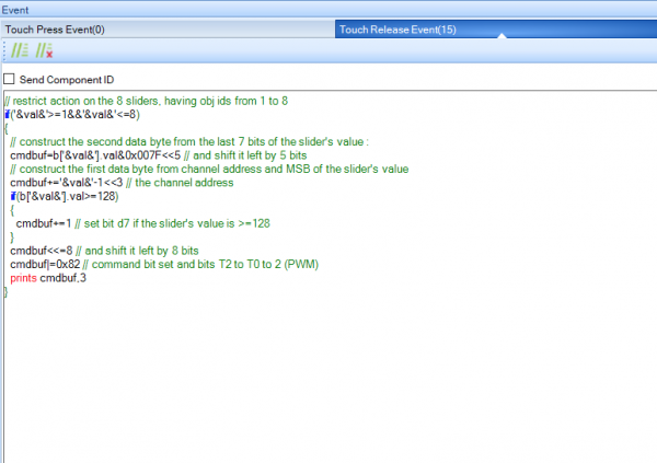
For the PWM1 page with 8 sliders, things look like this:
// restrict action on the 8 sliders, having obj ids from 1 to 8
if('&val&'>=1&&'&val&'<=8)
{
  // construct the second data byte from the last 7 bits of the slider's value
  cmdbuf=b['&val&'].val&0x007F<<5 // and shift it left by 5 bits
  // construct the first data byte from channel address and MSB of the slider's value
  cmdbuf+='&val&'-1<<3 // the channel address
  if(b['&val&'].val>=128)
  {
    cmdbuf+=1 // set bit d7 if the slider's value is >=128
  }
  cmdbuf<<=8 // and shift it left by 8 bits
  cmdbuf|=0x82 // command bit set and bits T2 to T0 to 2 (PWM)
  prints cmdbuf,3
}
For the PWM2 page, things are almost the same, just the number of sliders and the channel address offset change:
// restrict action on the 8 sliders, having obj ids from 1 to 4
if('&val&'>=1&&'&val&'<=4)
{
  // construct the second data byte from the last 7 bits of the slider's value
  cmdbuf=b['&val&'].val&0x007F<<5 // and shift it left by 5 bits
  // construct the first data byte from channel address and MSB of the slider's value
  cmdbuf+='&val&'+7<<3 // the channel address
  if(b['&val&'].val>=128)
  {
    cmdbuf+=1 // set bit d7 if the slider's value is >=128
  }
  cmdbuf<<=8 // and shift it left by 8 bits
  cmdbuf|=0x82 // command bit set and bits T2 to T0 to 2 (PWM)
  prints cmdbuf,3
}
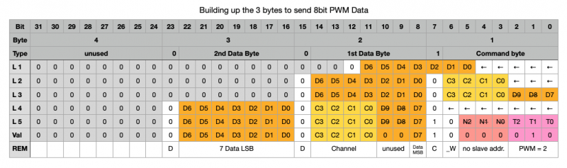
Now, I understand that this code which is compact and highly efficient might be difficult to understand. Thus, here a table which shows how all this adding and bit shifting works, step by step:
Here is the complete HMI project file (which will still see extensions for GPIO, ADC, and more over the next weeks) to study, to play around with and to check the output with the Nextion Debugger in case you don’t trust me 😉 : mega_io_ext.HMI
Next time, we’ll write some code for the Arduino Mega, so that it can receive and decode our NexMegaIO protocol and act accordingly.
For today, thanks for reading and happy Nextioning!
Questions, comments, critics, suggestions? Just send me an email to thierry (at) itead (dot) cc! 🙂
And, by the way, if you like what I write, and you are about to order Nextion stuff with Itead, please use my referral link! To you, it won’t make a change for your order. But it will pay me the one or the other beer or coffee. And that will motivate me to write still more interesting blogs 😉


