The Nextion MEGA IO project – Part 1
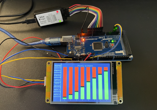
As announced in my last Sunday’s blog post, we’ll start from this week with the Nextion MEGA IO project which will allow us from a simple Nextion HMI without onboard GPIO, to write all the 12 PWM pins, to read and write all the 32 digital IO pins, and to read all the 16 analog pins of an Arduino Mega! Later, we will even add the option to control the full IO not only of one single MEGA, but several of these. We will also get a downsized version for the Arduino Uno. With the knowledge and tools given successively in this blog post series, you should become a master when it comes to using any MCU for connecting various sensors, LEDs, motors, fans, pumps, relays, or whatever you might imagine!
This project was born based on reader’s feedback after the Arduino PWM control from simple HMI post where the Nextion HMI controlled a RGB LED connected to an Arduino UNO. When publishing this, I had thought that this would be enough as an “idea giver” and as a kind of signpost, so that based on this, people would create their own extensions for their more complex projects (bottom-up development). But finally, most people who wrote me wanted a more exhaustive solution where the Nextion HMI would not only write to peripherals through the Arduino, but where the Nextion would also be able to request readings from peripherals in order to process or display these. So, I started imagining the most complex scenario which would cover literally everything and people could then simply comment out or delete the superfluous (for their specific project) stuff, which is called top-down development.
Thinking about a protocol
As two humans who want to communicate need a common language, two processors which want to exchange data need a common protocol. As you know, the Nextion HMI has its own language or protocol, the Nextion language. And there are existing libraries which allow the Arduino or any other MCU to speak and to understand the Nextion language, so this could be a simple approach, I thought first. But after imagining that I want to monitor many analog pins (where the information would probably be displayed on several different pages) I started wondering if having the Arduino Mega send for example “pageX.nY.val=1004ÿÿÿ” (=20 bytes) for a single analogRead(pin), and this multiplied by 16 for all analog inputs, was a good idea. Especially since the Arduino would need to know beforehand if pageX was currently displayed, so that it made sense to send this data, and it would also need to maintain a kind of dictionary to know the pageX and nY values associated to each analog pin. And we haven’t even yet thought about doing all this
“All that should be greatly simplified”, I thought, and I went back to the much simpler one-way, two bytes protocol used in my earlier PWM control project and decided to start from there. There is no need to reinvent the wheel, there are many common protocols (UART, I2C, SPI, etc.) and we’ll just have to do some cherry-picking to tinker an optimal solution for our specific needs together.
Command or data? Read or write?
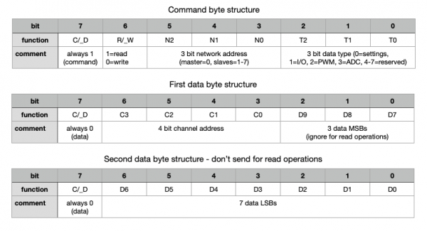
Inspired by previous projects and by the MIDI protocol, I decided to maintain the separation between command and data bytes. Thus, if an incoming byte is identified as a command byte, somme data bytes may follow but no terminator is needed. That saves already 3 bytes each time, compared to the Nextion protocol. As for the Midi protocol, we define that if the most significant bit (bit7) in the byte is 1, it will be interpreted as a command byte, and if it’s 0, a data byte. Second, we’ll need a bit which tells us if the command byte will send data afterwards (write operation) or if it’s a request from the other side to send or write data. Inspired by I2C, we define the second most significant bit (bit6) to be 0 if this is a write command which means that the data to write will be sent directly afterwards, while an 1 at this place will indicate the other side that it has to write, now. Thus, the first 2 of 8 bits in the command byte are defined. Let’s see what to do with the remaining 6:
A network address?
As said above, we want to keep the option to use multiple MCUs to extend our GPIO to >100 channels, thus, we need a few bits to care about slave addressing. Let’s assume that a total of 8 MEGAs should be enough, then 3 bits (bit3 to bit5) to encode the addresses 0 to 7 (binary 000 to 111) are sufficient. On top of that, let’s define that the address 000 is always the “master”, the one where the Nextion HMI is physically connected. The advantage of this is that the receiving device will know from the first byte if the message is for it or if it should be immediately be sent out to a slave, including the following data bytes. That reduces latency since we haven’t to wait for the end of a message to decide and retransmit everything.
The data type must be indicated!
Actually, we have 4 data types to handle: PWM, digital I/O, analog (ADC), and settings. But we’ll again keep the option to extend this later, for example to deal with sensors or other interfaces connected for example to SPI, I2C, or the oneWire bus. Thus, we define the remaining 3 bits in the command byte to be the data type indicator: 000 for settings, 001 for digital I/O, 010 for PWM, and 011 for analog (ADC). The remaining 4 bit combinations 100 to 111 remain for the moment reserved for later extension.
We aren’t yet ready…
Although we managed to pack a huge amount of information into the command byte, this might not be sufficient. Let’s say we want to do a PWM write to Pin13 on the MEGA which is the PWM11 channel and set the value to 248. From this, and with all the details above, we can already combine the command byte: bit7 is always 1 for commands, bit6 is 0 since it’s a write operation, bit5 to bit3 are all 0 since we address the master MCU, and bit2, bit1, and bit0 are 0, 1, 0 respectively, since it’s a PWM (or any other analogWrite()) operation. How can we tell which PWM channel is exactly to be addressed? We have 12 PWM channels, and 16 analog inputs, thus 4 bits are needed to address them. And what about digital I/O where we have 32 pins or channels? Will we need a 5th bit? No! Each digital I/O can only take the value of 0 or 1, a single bit. We will not waste a full 3 byte sequence to transmit a single bit! We’ll organize our 32 I/O pins in 4 banks of 8, so that the values of 8 pins can be transmitted at once in a single byte. This saves a lot of transmission time and bandwidth, and 2 of our 4 channel bits are enough to address the corresponding bank.
The data bytes
Per definition and for the sake of identification, the MSB (bit7) of a data byte is always 0. That leaves us with 7 bits (bit6 to bit0) to effectively transmit data in each. On the Arduino UNO and MEGA, PWM can take values from 0 to 255, which requires 8 bits. Since our digital I/O is organized in banks of 8, 8 bits will again be sufficient. But analogRead() returns values from 0 to 1023 which requires 10 bits. Together with the 4 bits for channel addressing, this makes a maximum of 14 bits which fit exactly into 2 data bytes. Thus, if the command byte is a write operation, it will be always followed by two data bytes, containing the channel address and the 8- or 10-bit data. A read operation will not transport data, since it is a request for the other end of the line to send data, thus the command byte will only be followed by a single data byte which contains the channel address while the other bits will be ignored. A full forth-and-back is then a read request (2 bytes), answered by a write operation (3 bytes). That makes 5 bytes in total, in opposite to 20 bytes already one-way when using Nextion commands. Aren’t we efficient? 😉
Phew…
This were many words and detailed explanations. Let’s try to resume this in a few graphics:
As you can see – many words and thoughts, but a highly efficient and compact protocol as we’ll see in my next blog post when we’ll implement this on both sides in code – on the Arduino and on the Nextion HMI. Unfortunately, “compact and efficient” does not mean fool proof, it allows for example write operations on analog inputs, that (and a few other cases) will be handled in the code, so that invalid commands will simply be ignored.
For today, thank you for your patient reading and happy Nextioning!
Questions, comments, critics, suggestions? Just send me an email to thierry (at) itead (dot) cc! 🙂
And, by the way, if you like what I write, and you are about to order Nextion stuff with Itead, please use my referral link! To you, it won’t make a change for your order. But it will pay me the one or the other beer or coffee. And that will motivate me to write still more interesting blogs 😉


