Arduino PWM control from simple Nextion HMI
Three weeks ago, I published an article about simple serial communication from a Nextion HMI towards an Arduino, so that the latter could handle 25 buttons on a screen with only a handful of code lines. This was intended to show that for many simple use cases, there is often no need for using a complex library and the Nextion protocol with its variable message lengths and the famous 3 x 0xFF terminator. The week after, I went on, this time showing a simple event handler for the Arduino, so that it could process events auto-generated by the Nextion, just by enabling the “Send Component ID” case for all components. Thus, no Nextion-side coding was required. Since then, we were bound to the Nextion return data format, the Arduino side code was somewhat more complex but still shorter and simpler than using a library.
Nevertheless, it seems that did not so much trigger the interest of you, my dear readers, the click rate was only about 60% of the article before. From which I conclude that you prefer simpler solutions… Lets get back to a more basic approach, allowing to simplify things by sending only two bytes, a command byte and a data byte, and make it fool- and accident-proof without a terminator sequence.
Protocol thoughts
Following the KISS principle (Keep It Simple and Safe), just assuming that the first byte arriving was the command byte and the second one the data byte is simple but not safe. What if one byte did not arrive, being lost “on the road” during startup or because of transmission quality problems? All the following data would be misinterpreted.
Thus, we need a kind of “flag” marking a byte as THE command byte. Such a flagged byte allows us to understand that this starts a new sequence, independent of what happened before. To be still more safe, we should then check the following byte and make sure that it does NOT have the flag. Only if these two conditions are present, we can be sure that we have received a valid combination of a command and a data byte.
And… why re-invent the wheel? Let’s take some inspiration from the MIDI protocol: There, command bytes always have a value between 128 and 255 while data bytes always have a value between 0 and 127. Using the same mechanism, and knowing that for our purposes, there will – in opposite to MIDI – always only one data byte after a command byte, we’ll be quickly set up!
The RGB PWM project
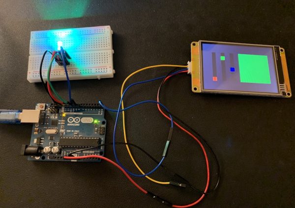
On the Nextion HMI side, we’ll need a screen with 3 sliders, one for each color component, red, green and blue. Each slider should take values from 0 to 127, according to our data byte range. Thus, we set their attributes as follows: .minval = 0, .maxval = 127, and .val = 64 (the default value). As a bonus, we add a text component without text and we’ll update its .bco (background color) attribute according to the three sliders’ position as a color monitor.
Each slider will thus have similar code in the TouchRelease code pane, first to calculate the new monitor’s .pco value and then to send a command byte, followed by a data byte which is the slider’s value. We just have to define the values for the command byte which each slider is sending and we chose 129 for slider h0 (red), 130 for slider h1 (green), and 131 for slider h2 (blue). Here, as an example the TouchRelease code for slider h0:
// transform the slider values into a RGB565 color
sys0=h0.val>>2 // reduce from 7 to 5 bits for Red
sys1=h1.val>>1 // reduce from 7 to 6 bits for Green
sys2=h2.val>>2 // reduce from 7 to 5 bits for Blue
t0.bco=sys0<<6+sys1<<5+sys2 // assemble everything to a 16bit color
prints 129,1 // send the command byte
prints h0.val,1 // send the data byte
To make the color change visible in real time even during each slider’s moving before we release it, we add a single line in the TouchMove code pane to trigger the execution not only on release, but already during a move:
click h0,0For the two other sliders, it’s pretty much the same, please have a look onto the .hmi file linked at the end of this article.
There is also some code in the page PostInitialize event to send the current (default) values of the 3 sliders to the Arduino:
delay=1000 // wait for the Arduino Uno to be ready
click h0,0
click h1,0
click h2,0
The Arduino side
Hardware-wise, we will have to connect a RGB-LED to three PWM capable pins. We chose pin11 for red, pin10 for green, and pin9 for blue and we declare this to the code with three #define tags at the very beginning of the code. Afterwards, we have to look onto the incoming command bytes to understand for which color/pin the following data byte is intended, and use the analogWrite() function with the data byte to set the PWM output signal accordingly – almost! We shouldn’t forget an important thing:
The values which we get from the sliders are limited to the 0 – 127 range, but analogWrite() expects values between 0 and 255 to cover the full range. The Arduino’s built-in map() function would allow us to “stretch” the range, but in past projects, I found that the map() function is slow because it uses several additions, subtractions, a multiplication and even a (slow) division to do something which is called “linear interpolation”. While this works well and we could definitively use analogWrite(pin, map(drain,0,127,0,255) I found that being a huge overkill and I preferred to add my much simpler and quicker upscale() function to the sketch.
The result is the same, but we get away with only 3 logical operations, two bit-shifts and a logical OR to implement a fractional multiplication of the input by 2.0078125 which has exactly the same effect, extending the input range from 0 – 127 to an output range from 0 – 255. So, here is the first part of the Arduino code:
// The pins for connecting the RGB LED
#define pinR 11
#define pinG 10
#define pinB 9

// The variables for the 2 byte protocol handling
byte cmdIn=0,dtaIn=0;
bool cmdOk=false,dtaOk=false;

// The "helper" function which replaces the map() function here
byte upscale(byte in) {
  in &= 0x7F;  // make sure we have a 7bit input (0-127) to prevent overflow
  return (in << 1) | (in >> 6);  // do the magic ;-)
}

void setup() {
  // put your setup code here, to run once:
  Serial.begin(9600);
}
No rocket science, up to now! In the loop(), we’ll have to handle incoming bytes (if there are) by distinguishing between command bytes (> 127) and data bytes (all others/else). These are then copied into cmdIn (the command byte) and drain (the data byte). We use two boolean flags cmdOk and dtaOk to make sure that only command bytes followed directly by a data byte will be considered as a valid sequence, having both flags set to true. Finally, depending on the command byte’s value (129, 130, or 131), use analogWrite() with the corresponding pin and the upscaled value to change the RGB LED’s color:
void loop() {
  // put your main code here, to run repeatedly:
  if (Serial.available()) {
    byte tmp = Serial.read();
    if (tmp > 127) {  // it's a new command byte and we have to wait for a data byte
      cmdIn = tmp;
      cmdOk = true;
      dtaOk = false;
    } else {  // it's a data byte
      if(cmdOk){  // we will only take it into account when there was a command byte before
        dtaIn=tmp;
        dtaOk = true;
      }
    }
  }
  if(cmdOk && dtaOk){
    switch (cmdIn) {
      case 129:  // command byte for red
        analogWrite(pinR,upscale(dtaIn));
        break;
      case 130:  // command byte for green
        analogWrite(pinG,upscale(dtaIn));
        break;
      case 131:  // command byte for blue
        analogWrite(pinB, upscale(dtaIn));
    }
    cmdOk = false; // reset everything
    dtaOk = false;
  }
}
And that’s it! Feel free to play around with it. It simply works as you can see on the picture above.
Here is the .hmi file for the Nextion: arduino_rgb.HMI
And here is the .ino file for the Arduino: arduino_rgb
Thank you for reading and happy Nextioning!
Questions, comments, critics, suggestions? Just send me an email to thierry (at) itead (dot) cc! 🙂
And, by the way, if you like what I write, and you are about to order Nextion stuff with Itead, please use my referral link! To you, it won’t make a change for your order. But it will pay me the one or the other beer or coffee. And that will motivate me to write more interesting blogs 😉


