Nextion HMI as an autonomous data logger with Data Record, GPIO and RTC
A classic data logger would use a MCU and its GPIO pins, a SD card, a RTC, an LCD status display and many lines of code. Today, I’ll show you that you can have all in one, using a Nextion Intelligent series HMI and thus reduces cost and development time: First, the Intelligent series has everything “on board”, the MCU, the GPIO pins, the RTC, the screen, and the SD card. Second, a very powerful component, the Data Record is available for these HMI displays in the Nextion Editor, which saves us, let’s say around 500 lines of C code. But telling you this is one thing, giving you a demo project at hands which covers all functionalities and which you can modify and extend as you need for your project is today’s topic.
What is a data logger ?
A data logger is a device which records events, together with a corresponding timestamp, so that you can see afterwards what happened, and when. Complex data loggers may use sensors for almost everything, humidity, temperature, altitude, inclination, distance, but controlling this kind of sensors requires most times a data bus like I2C or SPI which is beyond the Nextion’s connectivity. But simple sensors, including simple switches, triggering for example when your rain water collector bucket is full, when your heater pellets stock is empty, when someone walks on a contact or through a light sensor, or when someone/something moves within the field of an IR sensor – every time you have a logic signal like the closing of whatever contact which pulls a GPIO pin towards GND – can perfectly be handled by an Intelligent Nextion without additional peripherals besides the handful of switches.
The hardware
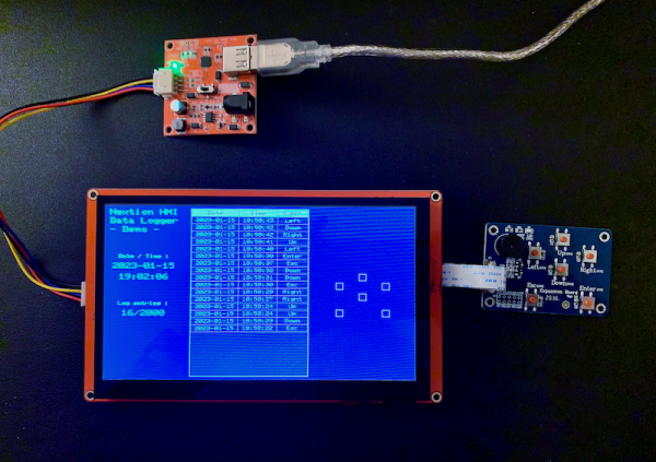
To ease the wiring for this demo project, I decided to use the Nextion I/O Extended Expansion Board because it’s easily connected to our Nextion screen with its flat ribbon cable and because there are already 6 momentary switches soldered on it. For your own projects, the Nextion I/O Adapter might be the better option since it connects through the mandatory flat ribbon cable too, but then brings out the I/O lines to pin headers, so that you can easily add your required sensor contacts.
The GPIO interface
The 6 switches on the expansion board are momentary switches which means that they close the contact between the corresponding I/O pin and GND when pressed and they open it when released. The Nextion programming environment does not allow binding event code directly to an I/O pin, only reading (for inputs) and writing (for outputs). But there is a mode to bind an IO pin to a component, so that a falling logic level (from 1 to 0 like closing a contact to GND) will trigger a TouchPress event in the bound component, and a rising logic level (from 0 to 1 like re-opening the contact from GND) will trigger a TouchRelease event. This allows us to put the desired event code into the corresponding TouchPress and TouchRelease event code panes.
If you do not want to have a visual component for each I/O pin on your screen, feel free to use Hotspot components and to hide these behind other components to prevent accidental triggering by touching the screen. But I wanted the visual version. That’s why I placed 6 Button components in the right third of the screen – arranged in a similar way as the switches on the expansion board. I left them without text, just gave them a border and the same background color as the underlying page. When pressed – either manually or through the signal change an the bound GPIO pin, the color turns to light green for visual feedback. But since this project is not made to press the screen buttons (except for testing and debugging purposes), I made them small. In case you want absolutely to prevent the button touch press from the screen while keeping the visual aspect, there is still the option to add an if() clause which reads the GPIO pin level via the corresponding piox system variable and to execute the TouchPress or TouchRelease event code only if the GPIO level corresponds.
To make the code better readable, I gave these 6 buttons the same object names as the labels on the expansion board: Esc, Enter, Right, Down, Up, Left. The binding with the GPIO pins is configured in the page PreInitialize event, using the cfgpio command:
//configure IO0 to IO5 as inputs, bound to the screen buttons
cfgpio 0,1,Esc
cfgpio 1,1,Enter
cfgpio 2,1,Right
cfgpio 3,1,Down
cfgpio 4,1,Up
cfgpio 5,1,Left
Generating the time stamp
The Nextion Intelligent (and Enhanced) HMI screens have an integrated RTC. It can be adjusted from the PC, using the Nextion simulator/debugger from the Operation menu, using the Nextion Device RTC calibration function. Don’t forget to insert a CR1220 battery into the socket of the Nextion’s back side to keep the RTC running and up-to-date even when powered off! You may also add a setting screen to set the system variables as follows: rtc0 => 4 digit year, rtc1 => 2 digit month, rtc2 => 2 digit day, rtc3 => 2 digit hour (24h format), rtc4 => 2 digit minutes, and rtc5 => 2 digit seconds.
In this demo project, we assume that the RTC has been correct set from the debugger/simulator and the code just reads periodically the rtcx system variables to assemble two strings, a date string and a time string, which are to be stored and displayed in two Text components, t2 and t3. That’s also from where the data will be taken when an event to be logged occurs.
To minimize display jitter and flickering, there is a timer named clock which reads the RTC every 330ms and assembles the corresponding date and time strings, using the covx function, simple string concatenation and a few helper text Variable components, named s_date, s_time, and s_tmp. But t2 and t3 will only be updated if the newly generated strings are different. Here is the timer event code:
//query the date variables and assemble the date string:
covx rtc0,s_date.txt,4,0
s_date.txt+="-"
covx rtc1,s_tmp.txt,2,0
s_date.txt+=s_tmp.txt
s_date.txt+="-"
covx rtc2,s_tmp.txt,2,0
s_date.txt+=s_tmp.txt
//query the time variables and assemble the time string:
covx rtc3,s_time.txt,2,0
s_time.txt+=":"
covx rtc4,s_tmp.txt,2,0
s_time.txt+=s_tmp.txt
s_time.txt+=":"
covx rtc5,s_tmp.txt,2,0
s_time.txt+=s_tmp.txt
//update screen only if different to prevent flickering:
if(t2.txt!=s_date.txt)
{
  t2.txt=s_date.txt
}
if(t3.txt!=s_time.txt)
{
  t3.txt=s_time.txt
}
The Data Record component
The Data Record component is very powerful and it does most of the work by itself as we will see in the next paragraph. But it is important to set its attributes correctly. And that is not simple with this very long list of attributes in the editor. But I’ll give detailed comments on some key attributes below, while other, more common attributes like size, position and colors can be handled like for any other component.
Technically, the Data Record component in nothing other than a viewer for an underlying file, containing data. While this file may contain several thousands of records or rows, each containing a fixed number of fields, the visual component will just display an excerpt (the number of lines/rows which fits into the dimensions of the component on the screen) and the rest is available through simple scrolling. If it doesn’t yet exist on the SD card, it will create its corresponding data file with a size which allows to hold all the data depending on the following attributes: .length is the maximum number of characters per row (including field separators, see below) and .maxval, the total number of rows to be stored. In this project, I set .length to 63 which seems a bit exaggerated, but I wanted to leave some headroom for longer event descriptions, and .maxval to 2000, which means that 2000 events can be recorded. But what if the file is full? No, the 2001st event won’t be dropped and get lost. it will overwrite the oldest, the 1st event, and so on. This makes sure that the most recent history is always available.
You need more? No problem. Simply increase .maxval, compile and upload your project again! But take care: You risk to see an error message in the data record component because after your changes, the underlying file format and size will not longer fit. Simply delete the data file from the SD card (or in the virtual SD folder while you are working in the simulator/debugger) and the component will automatically create a new empty file with the correct format and size. Data file? Which data file? Just have a look onto the .path attribute and you’ll find something like sd0/1.data – that’s the answer!
Now, each row will be divided into several fields. For example, in this demo project, there are 3 fields per row: Date, time, and event description. That’s why the .dez attribute is set to 3. The Data Record expects fields within a row to be separated by a circumflex (^). Thus a typical record would look here like this: “2023-01-15^18:58:38^Enter”. The same applies when configuring the individual column widths with the .format attribute: 120^100^80 and when setting the column header text with the .dir attribute: “Date^Time^Event”. Last attribute to configure: .order which I set to 0-new data before. This makes that the newest entries are added on top and that older entries sink gradually down. Remember, if you want to see them, simply scroll down. All the other attributes may be left at their default values for the moment. I should just mention that there is one read-only attribute, .qty, which holds the current number of entries. It will automatically be incremented when a record is added. This allows us to display the number of log entries with our custom update function (see below).
Generating the log data
The log data is a record to be inserted into the Data Record component. It has thus the form “data0^data1^data2” and can be assembled by simple text concatenation as we do it in the TouchPress event code for each of the 6 GPIO bound buttons, before we call a common update routine which will insert the record and update the log entries display. Who says common routine says hidden hotspot. Thus, there is a hotspot in this project, named Update, and hidden behind the Data Record component. But one after the other… Each of the buttons TouchPress events will assemble a record, taking the current date string from t2, the current time string from t3, and some static event description text and write it into another text Variable component, called s_dline before the common update routine is called. Here is the example of the Esc button, the code is very similar for the other five:
//build the record to insert:
s_dline.txt=t2.txt+"^"+t3.txt+"^Esc"
click Update,1
The common update routine
That something like a function to be executed after one of the 6 GPIO events has happened and thus the event code of the corresponding button has been executed to generate le record or row to insert. First thing is naturally to really insert the row into the data record and to update afterwards the Log entries status in the Text component t5. The latter is simple done by assembling another string using again the covx function to display the current number of entries from the .qty attribute, a slash (/), and the maximum number of entries from the .maxval attribute:
data0.insert(s_dline.txt)
covx data0.qty,t5.txt,0,0
t5.txt+="/"
covx data0.maxval,s_logtmp.txt,0,0
t5.txt+=s_logtmp.txt
And that’s all. Isn’t it amazing that the longest code part is for building the date and time strings while the logging of a single event is less than 10 lines of code?
As always, here is the .hmi file for download. Please feel free to play with it in the debugger/simulator, to modify it, to play around with it, and to re-use it in your own projects: data_log_demo.HMI
I’m still thinking about another project which would allow us to retrieve the data file and to view and process it in a spreadsheet tool like Excel. Let’s see what the next Sunday will bring…
Happy Nextioning!
Comments, critics, suggestions? Just send me an email to thierry (at) itead (dot) cc or send me a message on Instagram (nextion_thierry)! 🙂


