Advanced programming
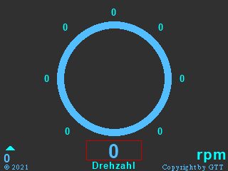
A reactive and flicker-free gauge
Everything started in a Nextion-related group on Facebook where a young man who is into motor tuning – let’s call him “M.” – asked for advice:
“Hey! I’m building a gauge with the “line” command. Now I’m searching a way, to find all correct X and Y of the outside circle. How can I do that ? I Just need every 3° so i have 120 X and 120 Y numbers. I also looked into the Sunday projects of Thierry Frenkel but I can’t get any way to understand, how to get this coords of a circle by itself an put it into a val.txt and read it with spstr. Maybe Thierry can help me with this ? By the way: I have to build this own gauge, because the nextion gauge flickeres too much. And if i use pictures 120 times it workes perfect, but the user can change the background color in settings, and then you have a Black rectangle around the gauge pictures.”
I replied: “There are at least 3 Sunday projects which deal with similar issues and which could easily be adapted to your project. Using some basic rules of trigonometry, one can easily break down the whole thing that you do not need 2 x 120 values but only 1 x 30 values to look up in a pseudo string array. I could help you with this. What I’d need is
– the center x and y coordinates of your pseudo-gauge,
– its radius,
– the “zero” direction (top, bottom, right, or left),
– the screen model you are using.
If I get all this info either here or via PN until this Wednesday, it will be the topic of the next Sunday Blog.”
He went on with details: “I’m glad to hear that. Would be very nice of your help. I Just looked up this 3 sunday projects, but it’s to difficult do understand your trigonometry formulas.
Screen size: 240 x 320
Centre: 160 x 110
Radius: 70
Zero direction is atleast buttom-left. so if you’re using the nextion-gauge it would be 310°. I used
cirs 160,110,80,maincolor
cirs 160,110,70,bgcolor
For this circle. On Postinitialize Event and it need to be drawn again on updating the gauge. I put a t0.txt in background with t0.bco=bgcolor. And so you can just ref t0 to “clear” the whole circles and lines, that the RAM is free. ref the whole page would be flickering”
Well, I thought, ok, that’s a nice challenge. And although M.’s ideas went into a good direction, it can still be improved…
The refresh dilemma
When having moving elements on your GUI, each time something alters its position, it must be deleted at the old position before you draw it at its new position. Deletion is often be done by refreshing the screen, or, in case of the out-of-the-box gauge, by refreshing the component. Think of a 140 x 140px gauge component, not only 19600 pixels have to be rewritten, the circle has to be re-calculated and redrawn, and if other components are superposed, these would have to be redrawn, too, in a second pass. That takes time. During this time, everything is first filled with the background color. Then only, the details are drawn on top. That’s what one sees as flicker. And since the background and the drawing colors must be customizable at runtime, you even can’t cheat…
M.’s approach with refreshing a Text component, and drawing two filled circles, a bigger one in the drawing color and a smaller one in the background color above to get the hollow circle in 10px thickness, reduces the problem. But nevertheless, each time the gauge’s needle changes its direction, there is still a lot of drawing to do. What I do in today’s demo project, is drawing the circles only once, in the Page PostInitialize event. Then, I draw the “needle” at its “zero” position.
Each time, the needle has to point into a different direction, I just “undraw” the old needle by redrawing it at its old position again, but in the background color. That’s only about 70 pixels to redraw instead of several thousands. Then, only the new needle must be drawn immediately, and flicker free, since the circles are still intact. Out of the huge time saving aspect, it saves memory, too, since you do not longer need the huge Text component in the background.
Sine and Cosine and the lookup table
No, Sinus and Cosinus aren’t the Roman soldiers in the Asterix comics 😉 These are so-called trigonometric functions which allow to get the x and y coordinates of a circle point for a given angle. Since the internal MCU of our Nextion HMI can not do the long and complex calculus for sin(x) and cos(x), at least not with reasonable effort and within reasonable time, M.’s idea to use a lookup table instead was right. I have shown how one can save number lists, separated by a special character, in a long string, beforehand, and use the spstr function to retrieve a specific value by its index at runtime. Since M. wanted 3° steps, we’d need 120 points (or 240 coordinate values, 120 x x and 120x y) which would make large lookup tables. Using the spstr function would be very slow in that case since the internal MCU would have to check each single character of the string, check if it’s a separator, move on, until arriving at the n-th and the n+1th separator, and extract the text in-between.
Using symmetries
When we look at a sine curve, we see a wave which is 0 at 0°, 0.707 at 45°, 1 at 90°, 0.707 at 135°, 0 at 180°, -0.707 at 225°, -1 at 270°, -0.707 at 315°, and 0 at 360°. For the cosine curve, it’s exactly the same, but it is somewhat shifted to the left, so that to starts at 1 at 0°, then 0.707 at 45°, 0 at 90°, and so on. So, from 0 to 90°, the first quarter of the circle, sine goes up from 0 to 1 while cosine goes down from 1 to 0. In the second quarter (90 to 180°), sine goes down from 1 to 0 while cosine goes down from 0 to -1. In the third quarter (180 to 270°), sine goes down from 0 to -1 while cosine goes up again from -1 to 0, and so on. To make this long story short, it is sufficient to know all the values for sine from 0 to 90°. Using the identity cos(x) = sin(90°-x), we have the corresponding values in the same list when we read it backwards from its end. M. wanted 3° steps, thus, for 0 to 90° we only need 30 elements in our lookup list an not longer 2 x 120
Is there a quicker way to retrieve the values from the list than with the spstr function?
Yes, there is. But before, we have to understand that sin and cos values are abstract fractional numbers between 0 and 1. To get the coordinates of a circle point, we have to multiply these with the circle’s radius. And since our Nextion HMI can only address integer pixel coordinates, it made sense to multiply the pre-computed values with the radius (70 as required by M.) and to round the result to the next integer. Thus, we obtain one- or two-digit numbers between 0 and 70, like {0,4,7,11,15,18, … ,67,68,68,69,70,70}. Most of these numbers have two digits. So, I thought that instead of writing these into a string with a separator character to make it indexable, I’d “waste” 3 bytes to transform the one-digit numbers in two-digit numbers, so that every element had the same length, and I’d then save 29 bytes of separator characters. Thus, my lookup string looks now like 000407111518…676868697070. Now, that every “element” is exactly 2 characters long, I find the first element (index 0) at position 0, the second element (index 1) at position 2, and so on. This makes that our Nextion HMI does not longer have to read the whole string and to look for separators, but the position of the element with index n is at 2n. And the other coordinate which has to be read from the end of the string is at position (58 – 2n). Knowing the exact positions already, we can use the much quicker substr function to retrieve our values.
And what about the sign and direction ?
In the demo project, I called the variable step for the 3° steps. But since M. wanted to have the zero position at the bottom left which corresponds to 315°, we have to add 15 steps to step and we obtain what is stored in dstep after handling the overflow (beyond 120). Then, we have the variable quadrant which is for the quarter of the circle (indicating us the sign and direction to apply from the raw lookup value) and which is obtained by dividing dstep by 30, so that we obtain a number between 0 and 3. Then, we break dstep down to the first quadrant by applying modulo 30 to itself. Now we have everything to retrieve the two numbers from the lookup table, to apply sign and direction, before we have still to add the center coordinates. Then, we can finally draw our line!
It sounds more complicated than it is. All the stuff is just 29 lines of code and I packed it into a hidden hotspot called draw, so that after setting a value for step (in the demo calculated from the displayed rpm value), click draw,1 will do all the magic, compute, delete the old needle and draw the new one:
dstep=step+15%120 // turn the whole thing by 15 steps to have the "zero" at 315°
quadrant=dstep/30 // detect the quadrant to handle the signs
dstep=dstep%30*2 // bring it down to one single quadrant for the two-digit lookup table
substr lookup.txt,found.txt,dstep,2 // find the 2 digits as txt
covx found.txt,look_up,0,0 // convert to number
dstep=58-dstep // reverse the direction to get the second value from the same lookup table
substr lookup.txt,found.txt,dstep,2 // find the two digits as txt
covx found.txt,look_down,0,0 // convert to number
if(quadrant==0)
{
  draw_x=160-look_up // subtract from center_x since x is negative/increasing in quadrant 0
  draw_y=110+look_down  // add to center_y since y is positive/decreasing in quadrant 0
}else if(quadrant==1)
{
  draw_x=160-look_down // subtract from center_x since x is negative/decreasing in quadrant 1
  draw_y=110-look_up  //subtract from center_y since y is negative/increasing in quadrant 1
}else if(quadrant==2)
{
  draw_x=160+look_up // add to center_x since x is positive increasing in quadrant 2
  draw_y=110-look_down  // subtract from center_y since y is negative/decreasing in quadrant 2
}else
{
  draw_x=160+look_down // subtract from center_x since x is positive/decreasing in quadrant 3
  draw_y=110+look_up  // add to center_y since y is positive/incresing in quadrant 3
}
line 160,110,last_x,last_y,bgcolor // delete the old line
line 160,110,draw_x,draw_y,maincolor // draw the new line
last_x=draw_x // save new values for future deletion
last_y=draw_y
Naturally, some variables need to be defined in program.s:
//drawing parameters (default values) may be altered later in a settings screen)
int bgcolor=12678,maincolor=2047
//temp parameters
int last_x=113,last_y=159,draw_x,draw_y,look_up,look_down,j,step=0,dstep,quadrant
// temp variable only for the demo, can be deleted
int k=0 // for the "pause" trick
page 0                       //Power on start page 0
The Page PreInitialize Event holds some code to apply the custom colors. This is important to do it in the pre-initialize event, to prevent the components from being drawn with their default colors and the being drawn again with the custom colors:
//Apply color style to all components
for(j=0;j<9;j++)
{
  rpmpage.b[j].bco=bgcolor
  if(j>0)
  {
    rpmpage.b[j].pco=maincolor
  }
}
And the Page PostInitialize Event holds the circle drawing and variable initialization:
cirs 160,110,80,maincolor // draw the background
cirs 160,110,70,bgcolor
click draw,1 // draw the zero line
// From here, it's for the demo code, can be deleted
j=80 // rpm step for the demo
demo.tim=15 // override the 50ms minimum
demo.en=1 // start the timer
The demo animation
… is controlled by a timer named demo. It increments the rpm value in steps of 80 (which corresponds to the 3° steps) every 15ms, calculated the corresponding step value and executes click draw,1 which does, as written above, all the magic. When the maximum (7200 rpm in this example) is about to be reached, the counter is reversed and rpm is decremented by 80 each run. The variable k is set to 40 after each direction change, inserting 40 timer cycles without any action (besides of decrementing k by 1), thus introducing the 40 x 15ms = 600ms break each time the maximum or minimum is reached:
if(k==0)
{
  rpm.val+=j //run the demo...
  if(rpm.val>7150||rpm.val<50)
  {
    j=0-j // reverse direction from the next run on
    k=40
  }
  step=rpm.val/80
  click draw,1
}else
{
  k-=1
}
And that’s it! The project file to play with, to modify it, and/or to adopt into your own project is here: alt_gauge_rpm.HMI
Happy Nextioning! 🙂


