Protocols and parsing – Part 5
Bit streams and block graphics
Recently, I read in a Nextion related internet forum the question of someone who asked for a solution where “an array of bits” would be sent to the Nextion HMI and the latter would then switch the corresponding pixel(s) on or off. My first thought was that the Nextion HMI wasn’t the ideal device to display monochrome block or pixel graphics. But after some considering, I decided that having such a functionality could give a nice visual effect, especially when not full screen. I then thought by myself that realizing such a project would basically be re-creating one of the numerous OLED libraries which exist for Arduino and other platforms in Nextion language – a good exercise and an occasion to shed some (pedagogic) light on the inner life of such a display driver.
And here we are… The central element of whatever display driver is the so-called frame buffer. For monochrome displays like OLEDs, it is dimensioned to hold one single bit per pixel. Besides very old graphic standards like CGA or EGA, most color applications require a frame buffer which can hold between 1 and 3 bytes per pixel, depending on the desired color depth. But let’s remain monochrome for the moment and for the sake of easier understanding.
How it’s usually done
In a classic approach (Arduino or something alike driving an OLED), there is some RAM to be reserved for the frame buffer. Most time, it’s the OLED driver (which by itself calls a graphics library to fill the buffer and a transport library like I2C/Wire or SPI to send everything out) which cares about that. Thus, the “effect chain” is as follows:
High level drawing commands => Graphics library => Frame buffer => Display driver => Transport library => Bus (I2C or SPI) => Display
Thus, the main task of the Display driver (or library) is calling and setting up the full chain, so that the drawing commands appear as member functions of the display object. Then it has to dimension the frame buffer to make sure that it corresponds to the physical display resolution. Finally, it has to send all the initialization commands to the display before it can take the (in the meantime filled) frame buffer, format the data accordingly, and send it out to the display.
By simulating this with our Nextion HMI, we’ll split the task up: We’ll render the screen content elsewhere and then send the corresponding bit stream to the Nextion. Here, the serial buffer in protocol reparse mode will act as the frame buffer and finally, some code in Nextion language will “mirror” the content of the frame buffer to the real display.
Limits of our experimental approach
On most Nextion HMI displays, the size of the serial buffer is 1024 bytes, corresponding to 8192 bits which makes a frame buffer for 8192 pixels. But even the smallest Nextion has a resolution of 320 x 240 = 76800 pixels. Thus, we cant’t send a full picture in full resolution. By introducing a scale factor (the variable raster in the demo project below), a single bit does not forcibly highlight one single pixel, but a small square of n x n pixels. Thus, for example with a raster of 10, 32 bit width and 24 bit height, we can fill our screen entirely! And we’d need only 32 x 24 = 768 bits or 96 bytes. That’s the approach which I selected for the demo project. But it remains flexible – you might set a raster size at your convenience. Or you set it to 0 which will make that the code calculates the raster size by itself to fill the whole screen at the best.
The container trick
Like for initializing a graphics object on an external MCU, we need some pre-initialized global variables. In our case, there are 4 of these: The horizontal extension (width) in virtual pixels or bits, same for the vertical extension (height), the plot color (of the highlighted pixels), and “raster” (our stretch factor). These could be declared and initialized inside the program.s file and doing so is perfectly fine. But I use this occasion to do it in a different way, so that these will look more like object properties. For this, we add a page to our project and we call it set. Then, we add four variables to it, calling these pco, w, h, and raster and we set them all to global. Now, from program.s or elsewhere, even from outside at runtime (in an extended variant of this demo project), we can set the attributes like this:
set.pco.val=2047 //Plot color of the dots
set.w.val=32 //Number of horizontal dots
set.h.val=24 //Number of vertical dots
set.raster.val=0 //Height and width of the dots, set to 0 for auto size
Looks nice, although it isn’t mandatory at all, but I thought that I’d show it.
Then, there are some variables needed at runtime to loop through the bytes of the serial buffer, through the bits inside each byte, and through the “true” rows and columns (the virtual pixel times the raster). The whole content of program.s is here:
//Helper variables
int ptr_u=0 //Serial buffer index
int ptr_x=0 //Horizontal index
int ptr_y=0 //Vertical index
int frame_bytes //Number of bytes to wait for a full picture
int tmp1,tmp2

//Static definitions, customize at your convenience
set.pco.val=2047 //Plot color of the dots
set.w.val=32 //Number of horizontal dots
set.h.val=24 //Number of vertical dots
set.raster.val=0 //Height and width of the dots, set to 0 for auto size

page 0                       //Power on start page 0
Page 0, the start page, is our drawing “canvas”. It’s simply black (or to whatever background color you’d like to set it) and it has no visual components. Just a timer which looks every 50ms if the frame buffer is well filled which means that there are as many many bytes as expected, an if yes, will proceed to the drawing. But before, in the Page PostInitialize event, there is some calculus to do: In case the raster was set to 0 (auto size), it has to be computed to fill the screen. Then, from the height and the width, the number of bytes for a full picture or frame is computed (the frame_bytes variable). Finally, the active protocol parse mode is activated, the serial buffer cleared, and the screen cleared. Then, frame_bytes is sent over serial to the external MCU, so that it knows how many bytes it must send to fill the screen. Now, the timer is enabled and waits for the MCU (or whatever) to fill the buffer:
//Initialize the drawing parameters
if(set.raster.val==0)
{
  tmp1=page0.w/set.w.val //check horizontal raster size
  tmp2=page0.h/set.h.val //check vertical raster size
  if(tmp1<tmp2)
  {
    set.raster.val=tmp1
  }else
  {
    set.raster.val=tmp2
  }
}
frame_bytes=set.w.val*set.h.val/8
//Switch to active protocol parsing and clear the buffer
recmod=1
baud=115200
tmp1=usize
udelete tmp1
cls page0.bco
//Request the required number of bytes
prints frame_bytes,0
//Start the processing
tm0.en=1
The timer’s event code will check if at least frame_bytes bytes are in the serial buffer and if yes, it will process it by first clearing the screen, then by looping through the the bytes of the serial buffer (outer loop) and through the bits inside each byte (inner loop with variable bit mask), and, if the corresponding bit is 1, draw a square in the preset pco color. Afterwards, the x-pointer is incremented, checking if a line wrap is required, and if yes, the x-pointer reset and the y-pointer incremented, until all bytes are processed – like in an original OLED library and/or the corresponding OLED driver IC. Finally, the processed bytes are deleted from the buffer, and again, frame-bytes is sent out to the external MCU, indicating that we are ready for the next frame:
//wait for a full frame in the buffer
if(usize>=frame_bytes)
{
  //clear the screen
  cls page0.bco
  for(ptr_u=0;ptr_u<frame_bytes;ptr_u++) { //process bit by bit tmp1=128 while(tmp1>0)
    {
      //apply bit mask
      tmp2=u[ptr_u]&tmp1
      if(tmp2>0)
      {
        //Draw the plot spot if corresponding bit is 1
        fill ptr_x*set.raster.val,ptr_y*set.raster.val,set.raster.val,set.raster.val,set.pco.val
      }
      //Move on
      tmp1>>=1
      ptr_x++
      //Line wrap
      if(ptr_x>=set.w.val)
      {
        ptr_x-=set.w.val
        ptr_y++
      }
    }
  }
  //Ready? Reset everything
  udelete frame_bytes
  ptr_x=0
  ptr_y=0
  //Request the required number of bytes
  prints frame_bytes,0
}
It’s neither black magic nor rocket science…
And now, how to get graphics data to be displayed?
In another blog article, I’ll show how a Arduino graphics library can be “(ab)used” to do the rendering for us before the generated data is sent over serial to our Nextion. But that’s a heavy task, please don’t expect it it for next week!
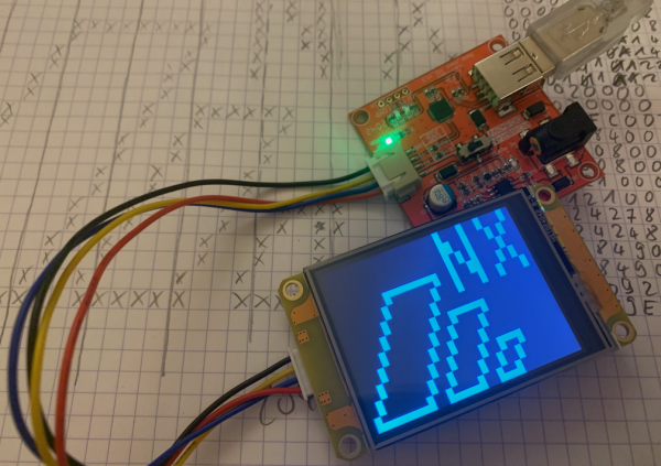
In the meantime, and for demo purposes, I did some rendering “by hand” with pencil and paper, as you can see in the background of the picture above. Using a 32 x 24 grid, I drew the desired screen content first, and then I went through it, line by line, noting the corresponding bitmaps and converting them to hexadecimal. This gave me the following 96 bytes:
00 00 11 22 00 00 11 22 00 00 19 14 00 00 19 14
00 00 15 08 00 00 15 08 00 FF 93 14 00 80 93 14
01 01 11 22 01 01 11 22 02 02 00 00 02 02 00 00
04 04 FC 00 04 04 84 00 08 09 08 00 08 09 08 00
10 12 13 C0 10 12 12 40 20 24 24 80 20 24 24 80
40 48 49 00 40 48 49 00 80 90 92 00 FF 9F 9E 00
To test everything, load the project into the editor, upload it to your Nextion HMI via serial, start the simulator, select “Nextion device” in the top toolbar and click “Connect”. While the simulator will try different ports and baud rates, some garbage may appear on the screen. When everything is connected and stable, touch the screen once, I’ve put a hidden reset function to clear and initialize everything again. If the reset is successful, you’ll see 60 00 00 00 in the MCU return window which indicates that 96 bytes are expected (32bit integer little endian). Then, above the Instruction Input Area, select “Hex”, paste the above bytes there, and click “Run all commands”. Then, your Nextion should show a pattern on the screen, similar to the one in the picture above.
Here is the project file: dot_matrix.HMI
Have fun playing around with it and happy Nextioning!


