The Sunday Blog: The enhanced “K” HMIs
Part 4: The EEPROM
As you might perhaps already know, the Enhanced (“K series”) and Intelligent (“P series”) NEXTION HMIs have a small (1kB) EEPROM memory space which allows permanent storing of numerical values or text strings, even at power loss. There are easy to use functions like repo, wepo, reps, and wept in the Nextion language to handle different forms of reading and writing.
To make meaningful use of it, there are a few things to know and to think about. That’s what this blog article is about.
EEPROM stands for…
Electrical Erasable Programmable Read-Only Memory. From which we see, that it is mostly made for reading out data. Partly in opposite to RAM (Random Access Memory) which can easily be a read and written, and looses everything when you stop powering it, EEPROM can still easily be read, it even keeps its data when powered off, but writing is a slow and extremely complex process. When using your Nextion’s EEPROM, you haven’t to care about details – the firmware does everything for you – but it’s extremely important to know that writing to an EEPROM means erasing a whole block of memory cells by applying a kind of over-voltage (all corresponding bits are thus set to “1”) before it can be rewritten by forcing some of the bits back to “0”. This stresses the semiconductor cells and that’s why the number of write cycles is limited. Usually, EEPROM cells wear out after around 10 000 write cycles and become unusable. Reading does not cause the same stress, so an EEPROM memory cell can be read millions of times without getting tired.
EEPROM should thus be used for…
Data which changes seldom or (almost) never and which needs absolutely to be retained when the device is powered off. A typical use case are for example Wifi routers where data like the network name and the password (and a few other parameters) are set only once and are modified at rare occasions only.
And how the Nextion handles it:
As I wrote above, the Nextion firmware cares about everything but for preventing wearing the memory cells out. That’s why you should never have write routines in a program loop – one logical error and the 10 000 writes are used within less than a second…
The EEPROM its just a linear storage of 8192 bits or 1024 bytes. Each byte can be a single numeric information, a text (ASCII) character, a part of a bigger (for example 32bit) number, or a longer text (String), but the EEPROM doesn’t have or retain information about that. It’s up to the firmware and to us developers to not to try reading a number at an address where we had previously stored a string or vice-versa. The repo or rept command will just return the bytes and if we messed it up, the result will look like garbage.
To help us getting things sorted, we have first to understand that there are internally two variants of the repo/repo commands. One takes numerical values, the other takes text strings. Numerical values are always handled as 32bit integers. Thus, when you execute wepo 1,0 to write the number 1 at address 0, it will first expand your number 1 to a signed 32bit integer which is 0x00000001 and then put it into 4 memory cells in little endian order, which means the LSB first. At address 0, we’ll have 0x01, while at address 1, 2 and 3, 0x00 will be written. Content which had been at addresses 1,2,3 will thus be overwritten. So, if we want to write another number, we’d need to write it at address 4 to prevent corruption of our previous number! For very small and positive numbers between 0 and 255, it would be a huge waste to block 4 memory cells for a single byte. There are packing techniques which I will explain afterwards.
Text strings take (normally) one byte per character plus a final 0x00 as a terminator. Why “normally”? Because normally, we use ASCII or ISO encoding where each character needs one byte. But when we use multi-byte encodings like UTF-8, the most common characters are also only one byte, but special characters might have more. Thus, it might be of interest to check the length of your text with the btlen command beforehand, which in opposite to the strlen command, does not count the number of characters in a string but the number of bytes these characters need for their representation. But let’s for the moment stay with ASCII: wepo “Mytext”,4 will write the bytes 0x4D, 0x79, 0x74, 0x65, 0x78, 0x74, 0x00 at addresses 4 to 10. 7 bytes for 6 characters because of the 0x00 terminator. Reading a string with repo into a text variable is then as simple as repo va0.txt,4. The 0x00 terminator helps the firmware to see when the string is complete.
Data packing
As written above, storing small numbers as 32bit integers wastes a lot of memory. That’s why there are techniques which allow to pack up to 4 bytes into a 32bit number. This technique is used in today’s example project, where we can save 4 settings between 0 and 100, set with the help of four sliders, in a single write operation. Because of the little endian format which stores the LSB at the lowest address, we start with setting our integer variable to the value of the first setting, let’s call it pp. It will thus look like 0x000000pp. Then, we use a bit shift operation to move our pp by eight bits or one byte to the left which will then look like 0x0000pp00. Then, a bitwise “or” operation with the next setting qq gives us 0x0000ppqq. Let’s shift again to obtain 0x00ppqq00, then bitwise “or” with the third setting rr and we have 0x00ppqqrr. Same, shift and “or” with the fourth setting ss, and we are at 0xppqqrrss, a single 32bit integer which contains all 4 bytes and which we can now write at address 0 and which will use the cells at 0 (pp), 1 (qq), 2 (rr), 3 (ss). Ready.
When we read that number back, we’ll need to unpack everything. A simple bitwise “and” with 0x000000FF will mask everything but the last byte out. So 0xppqqrrss “and” 0x000000FF will return 0x000000ss, our ss value. To get rr, we need a different mask, 0x0000FF00, before we have to shift the value right. 0xppqqrrss “and” 0x0000FF00 returns 0x0000ss00, so a right shift by 8 bits is needed to recover 0x000000rr. And so on. All that is used in our example project.
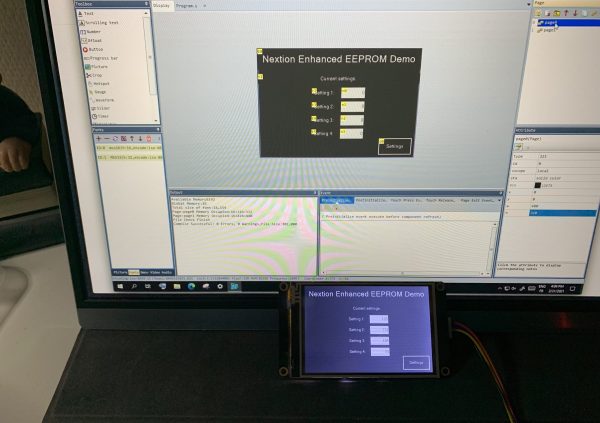
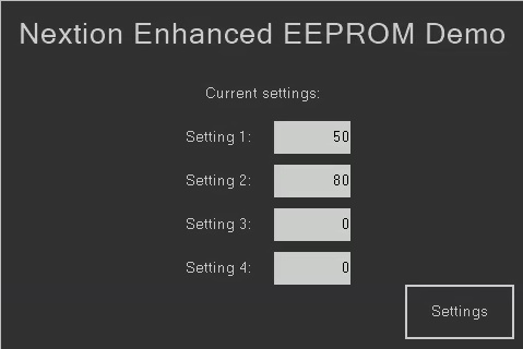
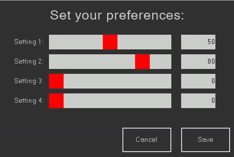
The example project
The example project consists of 2 pages. The first, a start page, reads the EEPROM and displays the 4 values. It features a settings button which allows to move to the settings page, where 4 sliders allow us to adjust the 4 values in a range from 0 to 100.
The page post initialize event code is pretty similar. The 32bit number is read from the EEPROM, unpacked, and the corresponding controls updated.
For the start page
// Read the EEPROM
repo sys0,0
// unpack the int32 into 4 bytes
n3.val=sys0&0x000000FF
n2.val=sys0&0x0000FF00>>8
n1.val=sys0&0x00FF0000>>16
n0.val=sys0&0xFF000000>>24
For the settings page
// Read the EEPROM
repo sys0,0
// Unpack the int32 into 4 bytes and display the result
h3.val=sys0&0x000000FF
n3.val=h3.val
h2.val=sys0&0x0000FF00>>8
n2.val=h2.val
h1.val=sys0&0x00FF0000>>16
n1.val=h1.val
h0.val=sys0&0xFF000000>>24
n0.val=h0.val
Then, still on the settings page there is some event code in the touch move and touch release events to update the corresponding number fields (just for user convenience and precision):
n0.val=h0.val
And finally the touch press event for the “Save” button. It packs the 4 slider values into a 32bit integer, reads again the EEPROM, compares and writes only back if both values are different to prevent unnecessary write cycles, before returning to the start page.
// Pack the 4 bytes into an int32
sys1=h0.val<<8|h1.val<<8|h2.val<<8|h3.val
// Read the actual EEPROM value
repo sys0,0
// only if these are different, write back to EEPROM
if(sys1!=sys0)
{
wepo sys1,0
}
page 0
That’s it. Download the HMI file here to play with it or to adapt it for your project: eeprom_demo.HMI
Thank you for reading, have a good week!


