Listen to your HMI
Serial communication basics
In the last days, I saw a post in a Nextion related German Facebook group. Someone, let him call R., complained about his Arduino code outputting data although the connected Nextion HMI was switched off. And even when he switched it on, it seemed that there was still unwanted data arriving and printed out by the serial monitor of his Arduino IDE. Without having seen a single line of his code, I understood what happened and I concluded from this that apparently, it is highly needed to shed some light on some fundamental principles of Arduino and other MCUs!
The difference between CPU and MCU
A pure CPU is a simple processor core with a few address and data lines. By itself, it can not do anything. You have at least to connect a clock generator, some program memory (ROM), some data memory (RAM) and some data input/output (GPIO) components to have it doing something almost meaningful like making a LED blink.
That sounds rather complicated because it asks you for setting up an elaborated hardware design with several ICs, just to see a LED blinking. And not only this, you’d have to write bare metal code as in the following symbolic example :
0000: load the base address of the GPIO register into a specific processor register
0001: load 00000000 into A (a general processor register)
0002: load 00001000 into B (another general processor register) //assuming that the LED is connected to the 4th GPIO pin of the external GPIO chip
0003: replace the value in A with the result of A XOR B //to toggle the polarity of the 4th bit in line
0004: copy the data in A to the GPIO register
0005: load 00000111 into E (another general processor register) // bare metal version of a loop which corresponds to delay(500) at 16MHz CPU clock
0006: load 10100001 into D (another general processor register)
0007: load 0010000 into C (another general processor register)
0008: check if C==0 – if yes goto line 0009:, else goto line 0011:
0009: check if D==0 – if yes goto line 0010: else goto line 0011:
0010: check if E==0 – if yes goto line 0002: else goto line 0011:
0011: decrement C by 1
0012: check if the carry flag has been set (happens when C rolls over from 00000000 to 11111111) if yes, goto line 0013: else goto line 0008:
0013: decrement D by 1
0014: check if the carry flag has been set (happens when D rolls over from 00000000 to 11111111) if yes, goto line 0015: else goto line 0008:
0015: decrement E by 1
0016: goto line 0008:
And that’s only the simplified symbolic variant… Some trial and error would be required to find the exact values to put into C, D and E to obtain a precise delay of 500ms, since a 8 bit CPU can not directly handle the required big numbers but 3 nested countdowns are needed to obtain a long delay. Thus, the time for a single loop execution is never constant…
In two steps to an easier life
Step 1 was the invention of compilers. Instead of handling single bits and bytes, computing jump addresses for the goto instructions in the code above, caring about which variables go into which processor registers, we could write our instructions in an abstract programming language like C or C++ without caring what happened inside the processor core.
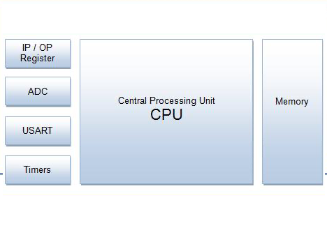
Step 2 was the integration of a CPU with multiple peripherals (Clock generator(s), Interrupt controllers, ROM, RAM, GPIO, UART, I2C, SPI, Timers, Counters, and much more) into a single IC: The MCU was born. Thus, things started to be standardized and even with complex functionality needed, a single IC like, for example, the ATmega328P in the Arduino UNO would give us everything we want.
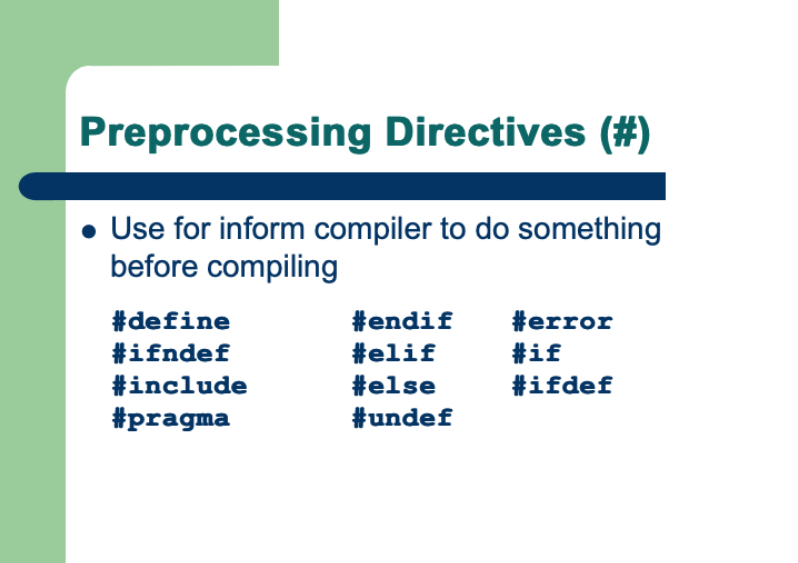
But… for a relatively long time, even with all the simplifications above, programming these beasts remained complicated. The C compiler would translate all sorts of computational commands, including conditional stuff like if(), for() and while() loops into more and more optimized bare metal code. But when it came to addressing the integrated peripherals like the UART (the serial port), you had again to look up the corresponding peripheral register addresses in the MCU’s data sheet and to learn which bits had to be set where so that the beast would communicate as you wanted. And these parameters were different for each MCU model and brand.
The Arduino revolution
It was the Arduino team which took the so-called wiring framework, a young open source project, and brought it almost to perfection. Instead of computing a divider factor from the CPU clock to apply the desired baud rate, to enable the UART building block, and to set protocol options, we only need to write
Serial.begin(9600);
but we do not longer see what happens behind this Arduino extension of the C++ language, all the computations and register settings to enable the serial communication. I can tell you that the Arduino framework includes between 50 and 200 lines of code, depending on the selected MCU brand and model, hidden under the hood of your .ino file. Already during boot of your UNO, the Serial object is initialized, sets up two 64 byte buffers, one for RX and one for TX, redirects the corresponding interrupt vectors towards its own handler functions, and so on. The Serial.begin is only the peak of a huge iceberg…
The advantage of the Arduino/Wiring framework is easy to see: It adds a so called HAL, a hardware abstraction layer, which allows us to address the integrated peripherals of the MCU without any detailed knowledge about these. Partly, the additional objects and functions are integrated in the framework’s core, like the Serial object for the UART, digitalRead() and digitalWrite() for the GPIO, analogRead() for the ADCs, analogWrite() for the PWM section of the Timer(s) or, for some MCUs the DAC(s). Others are available through easy to include libraries, like the Wire library for I2C or the SPI library.
Now, and with that, you do not longer need a university degree, nor weeks long study of the register documentation of a specific MCU, you simply call these high-level functions and be confident that the Arduino framework will translate this into the required bits and bytes which are very different between the Arduino Uno, Due, Mega, or Zero, just to cite a few examples.
The crux and the MCU architecture
There is no light without shadow, says a proverb. In the moment when your MCU does not behave as expected, especially since everything is fully encapsulated, it is sometimes complicated for the hobbyist to find the error, as R.’s case demonstrates.
It is important to understand that the UART (the serial port) and the CPU, although integrated in the same MCU, are separated and mostly independent building blocks. That means that the UART is permanently listening at the RX pin if signals arrive. If that is the case, it checks if an incoming signal fits with the selected protocol options, for example 1 start bit, 8 data bits, no parity bit, and 1 stop bit. If everything looks fine for the UART, it stores the 8 data bits as a byte in an internal register. All that happens without bothering the CPU which is most probably doing other things in that time. So, the UART needs to ring at the CPU’s door to tell that there is a byte which has arrived and that it has quickly to be stored elsewhere before the next byte arrives and overwrites the internal register of the UART. This is done with the help of an interrupt. As its name says, it will interrupt the CPU in whatever it is currently doing, and call an interrupt handler function which makes that the CPU reads the UART’s register and stores the byte in a 64byte buffer. Afterwards, the CPU will increment a variable by 1, so that other functions can check later if a byte is available for being read. Then, the CPU will return to the code which it was executing before the interrupt happened, not more and not less. All this happens very quickly within a few CPU cycles, and it happens in a hideaway from the currently running code, for example the loop() function on an Arduino (or the void main() function in other C/C++ environments).
You see it coming: Serial.read() does not read the incoming data from the UART directly, because we never know when data arrives, but it will read a value from the 64byte buffer. But what will it find there if there wasn’t yet an interrupt from the UART because no data has been received? That’s the mystery and at the same time, it’s part of the answer which we want to give R.
After that, we’ll have to understand how our code might know that there is incoming data which has been transferred from the UART to the serial buffer? That’s another mystery and the second part of the answer for R. which will then solve his “problem”.
And that’s what we’ll see next week! Stay tuned! 🙂
Thank you for reading and happy Nextioning!
Questions, comments, critics, suggestions? Just send me an email to thierry (at) itead (dot) cc! 🙂