The Nextion Editor: the Quick Review
This document goes through various features of the Nextion Editor. The Nextion Editor is used to rapidly create Human Machine Interface GUIs for Nextion HMI devices. As such the GUI can be created within Hours instead of Weeks, and Days instead of Months. So while we wont be covering basics such as opening a file, we will point out somethings that might prove helpful to know, or reminders need be made.
Requirements
- Windows Operating System (XP or higher). Users must know and be able to use their Windows OS. Windows support is beyond the scope of Nextion.
- .NET 3.5 Assemblies installed. When needed, download and install the .NET 3.5 Assembles from the Microsoft Website [here].
- Basic programming skills are prerequisite. The Nextion Instruction Set is made up of ASCII text based commands inbound, and binary Return Data. A component’s Touch Event “Send Component ID” can be used to defer programming tasks to the user’s MCU.
- As such, quickly creating an HMI GUI for Nextion does not demand extreme skills – but basic programming skill are expected. When programming logic Nextion side, then users should have a foundation in programming.
Note: Installations on other Operating Systems may have been accomplished successfully, but is not officially supported and beyond scope of any manual.
Downloading the Nextion Editor
The latest version of the Nextion Editor can be downloaded from [here].
There are two versions of the nextion-setup available for download.
- The EXE version is installed through the Windows MSI for a more automated installation. Only one version of the Nextion Editor may be registered at a time via the EXE version. When updating within the Nextion Editor, Auto Update will install the EXE version
- The ZIP version can be unzipped into a user chosen folder and run directly from that folder. For maintaining multiple versions of the Nextion Editor, the ZIP version is recommended. When updating within the Nextion Editor, Manual Update will launch your web browser to the download page so you may download the ZIP version
Want a more detailed version: try The Nextion Editor Guide
Part 1: The Editor Overview

- Title Bar
- a) Main Menu and b) Toolbars
- Picture Resource Pane
- ZI Font Resource Pane
- Page Pane
- Components Pane
- Design Canvas Visual Components
- Design Non Visual Components
- Attributes Pane
- User Event Code
- Display/Instruction Tabs
- Build Process Output
- Status Bar
1. Title Bar
- The Title – contains the full path to the currently loaded project
- If no project is currently loaded you can select a *.tft file to load with Debug
2. Menus and Toolbars.
- Compile – builds your project TFT file in the Nextion Editor/bianyi folder.
- File > Open Build Folder – opens the Nextion Editor/bianyi folder.
- Compiling a project from an older version creates a copy in Nextion Editor/backup
- File > Backup Dir – opens the Nextion Editor/backup folder.
- File > Import Project will append the imported project into your current project.
Currently Imported Project needs to be from version v0.29 and above. - Help > Help – launches the Nextion Instruction Set in your web browser.
- Up Arrow – sets the selected component to .id 1
- Down Arrow – sets the selected component to .id “highest” of N components.
- ID – toggles if the component .objnames are displayed in the canvas or not
A yellow objname has .vscope local, while a black objname has .vscope global. - All projects are compiled for a specific Nextion Model (except the 7″ Capacitive),
These settings are found in Device (Series, Model, Orientation, Encoding),
as well as setting the Project password to password protect the entire Project. - Debug will launch the currently loaded project in the Debug/Simulator.
If no project is currently loaded you can select a *.tft file to load. - About > About Nextion Editor – will show the Nextion Editor version.
- About > Check for New Version – will check if a new version exists.
- Tools > Font Generator – opens the Nextion Editor ZI Font Generator.
- Style – allows you to select between a Blue or Black Editor theme.
3. The Picture Resource Pane
- Be mindful when Exporting a highlighted picture. A *.jpg is lossy.
- Imported pictures are converted into 565 16 bit color format.
- Picture Resource Size is calculated: Width x Height x 2 bytes.
4. The Font Resource Pane
- Almost always, at least one *.zi font resource must be included in a project.
- Use the Tool > Font Generator to create a font, or an external font tool.
- To see a font’s content – highlight the listed font and click Preview
- Note the font’s size (width = 1/2 height, height % 8 = 0) is fixed width.
5. The Page Pane
- Each listed page contains a page index number and the page name
The page index number can be used for the p[index] array. - Double clicking on a page name allows the name to be changed
- Copy makes a complete duplicate of the highlighted page
Useful when creating a skeleton that will be reused in the whole project - Export allows a single page and its resources to be saved in *.page format
which is useful for sharing portions of an HMI. Import allows you to
import a *.page file into your project. - Pages can be individually password protected using Lock
6. The Component Pane
- Maximum 250 components can be placed on a page.
- New component is the QR Code, 84 chars on Ts and 192 on Ks
- Scrolling text component uses 1 timer
- Maximum of 6 timers per page – note scrolling text uses 1.
- Hotspot is a canvas component, but is not visually seen.
This makes it useful to hold event code for the click command - A Waveform is local component – never global
Up to 4 waveforms can be on a page. - Numeric .val can now also be entered in hex as n0.val=0x23432632
7. Design Canvas Visual Components
- Overlapping components (layering) can be complicated when not seen.
At design time, the lowest .id is the bottom layer, highest .id the top layer.
At run time, a refreshed component then becomes the top layer - Layering will produce component overlap warnings at compile time.
- Keyboard Arrow keys allow for moving a component by 1 pixel
- Left click to select a canvas component to avoid accidental movement.
8. Design Non Visual Components
- Only 6 timers are allowed per page – scrolling text components use 1 each.
- Variables can be numeric (4 bytes) or text (txt_maxl + 1 bytes)
9. The Attributes Pane
- Attributes pane has a dropdown list of components on the current page.
- The page component is always .id 0
- Attributes in black are read only at run time
- Attributes in green can be changed at runtime
- The .id attribute can be used for the b[.id] component array
10. The User Event Code Pane
- Touch Press and Touch Release events have Send Component ID.
Send Component ID is only sent with a physical touch - Touch Press and Touch Release code can be triggered with the click command
- Slider Components have an additional Touch Move
- A page’s Preinitialize is run before the page design is loaded
- A page’s Postinitialize is run after the page design is loaded
- Variable and Timer components do not have events
11. The Nextion Instruction Set
- The Instructions Tab will load Nextion Instruction Set (internal browser).
- Help > Help – launches the Nextion Instruction Set (external browser).
12. The Output Pane
- Warnings listed in blue – will compile, but perhaps unexpected behaviour
- Errors listed in red – will not compile. Do not upload a zero byte file.
- File Size must be small enough to fit in your Model’s Flash size.
- Stats for Global Memory usage are listed for the entire Project at top.
- Each page is compiled showing Memory usage: Global+Local=Total
- All pages Memory usage must be small enough to fit your model’s RAM
- Successfully compiled Project’s *.tft file is in Nextion Editor/bianyi folder
13. Status Bar.
- Current project settings: Encoding, Model, Screen Size, Flash Size, SRAM
Use the Device toolbar to change these settings if needed. - Current Mouse Coordinates
Part 2: Debug / Simulator Overview
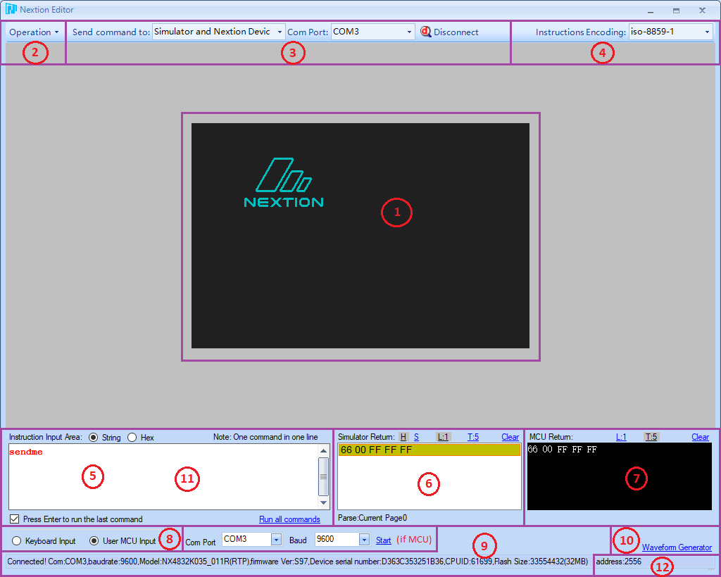
- Simulated Nextion
- Operations Menu
- Command Redirection
- Input Encoding
- Instruction Input
- Simulator Return
- User MCU Return
- Input Selection
- Connected Nextion Identification
- Waveform Generator
- Waveform Generator Options
- Nextion Address
1. Simulated Nextion
- This is a simulation – this is not an emulation.
- Purpose of the simulation is to aid in debugging commands
- Timers will not be precision under any Windows OS
- RTC is simulated, GPIO is not simulated
- EEPROM is simulated with file located Nextion Editor/eeprom.bin
- Note: EEPROM adheres to 4 byte boundaries when writing
Users may write to any address, but must care for data until boundary.
2. Operations Menu
- Upload, Synchronize RTC time and Reboot device.
3. Command Redirection
- Simulator only, Nextion device only, or both.
- Only Nextion or User MCU can be connected, not both
4. Input Encoding
- Character Encoding to use for input
5. Instruction Input
- text command input of any non-block Instructions (excludes if, for and while)
- Toggle hex mode to ensure byte precision in input.
(Answers the question of how to input less frequently used characters)
6. Simulator Return
- Any Return Data or print commands from Simulator will display here
- Expected to be sufficient to aid in the debugging process
- Not expected to be full trace logs (Simulator – not emulator)
- Options added in v0.53 of the Nextion Editor
View in Hex or String format
View Line by Line (ÿÿÿ terminations), or by Total bytes in Hex
Context Menu (right click) to: Copy HEX, Copy STR, Copy HEX+STR
7. User MCU Return
- Any Return Data or print commands from Nextion/MCU will display here
- Expected to be sufficient to aid in the debugging process
- Not expected to be full trace logs (Simulator – not emulator)
- Options added in v0.53 of the Nextion Editor
View in Hex or String format
View Line by Line (ÿÿÿ terminations), or by Total bytes in Hex
Context Menu (right click) to: Copy HEX, Copy STR, Copy HEX+STR
8. Input Selection
- Keyboard input is the default simulator input method.
- Toggle to User MCU input to have user MCU interact with Simulator
Select Com Port of user MCU, MCU operating baud rate and then Start - Only Nextion or user MCU can be connected, not both.
9. Connected Nextion Identification
- When Nextion is connected to Simulator, portions of connect string is shown here.
10. Waveform Generator
- Click here to show the Waveform Generator
11. Waveform Generator Options
- Sinewave or random waveform input at selected intervals.
- Expected to be sufficient to aid in the debugging process
- Not expected to be an oscilloscope (Simulator – not emulator)
12. Nextion Address
- 0 – Nextion normal mode, 256 to 2815 in address mode.
- Address will only apply to specialized advanced applications.