The Turbo Gauge with Nextion HMI
Improved needle design
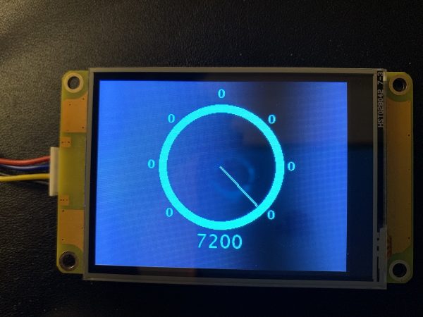
Do you remember the (almost) full screen sized flicker free and ultra rapid gauge we designed in June? And this without using the built-in Gauge component? If not, it’s time to read this article first, to understand today’s improvements. The June 2022 version does its job perfectly, the needle movement is quick and smooth, and other components can be added close to the outer circle without flickering since there is no background which needs constantly to be redrawn. But there was a minor and only esthetic weak point: The needle was a 1px thin line, sometimes difficult to see. Thus, already a short time after publishing, some readers contacted me and asked if there were a way to make the needle thicker, at least 2 pixels.
Hurdles and the solution
The center of the gauge is a point with fixed coordinates. With a 1px line, things are relatively simple as I demonstrated in the first version. Since the needle line starts always from the center, you’ll just have to find or compute the coordinates of the other end, draw_x and draw_y, undraw the previous line whose end coordinates were saved in the last_x and last_y variables, and then draw the new line. Simple and extremely efficient.
But what to do if the line has to be 2px wide? Drawing (and undrawing) a second line besides sounds trivial. But in reality, with a rotating line, “besides” means left, above, right, below, or a combination of these, depending on the angle. If we see the original 1px line as a vector, the desired second 1px line besides of it is the same vector, but shifted by an offset vector which is 1px long and which is orthogonal to our original.
As for the original needle, there is no need to compute everything for the whole 360° circle, we use trigonometric identities to break everything down to the first quadrant, the 0° to 90° range. Here, and since the orthogonal vector has a length of ~1px, only 3 value pairs occur: (0, 1), (1, 1), or (1, 0). Using another lookup table for this would be a waste and too slow, thus after declaring a bunch of new variables in an additional line of program.s as follows,
int ofs_up,ofs_down,cx,cy,tx,ty,last_cx=160,last_cy=110,last_tx=160,last_ty=110 //offset addition for a double line
we insert a if / else if / else clause into the drawing routine to set our offset vector (off_up, ofs_down), depending on the angle :
// offset calculation for the second line:
if(dstep<20)
{
  ofs_up=0
  ofs_down=1
}else if(dstep>=40)
{
  ofs_up=1
  ofs_down=0
}else
{
  ofs_up=1
  ofs_down=1
}
Implement the solution
Now, this offset vector has to be added (or subtracted, depending on the quadrant) from both, the start and the end point of the original line. Since we have no longer a fixed point to start from, we will have to compute 4 values for the 2nd line: The start x and y coordinates cx and cy, and the end coordinates tx and ty. Here, I show how this will be done for the first quadrant, for the details of the others, please download the HMI file at the end of this article and inspect the code of the draw hotspot.
  cx=160-ofs_down
  tx=draw_x-ofs_down
  cy=110-ofs_up
  ty=draw_y-ofs_up
As the original line, the second, parallel line will also have to be undrawn before a new is drawn, which explains the presence of last_cx, last_cy, last_tx, and last_ty in the above variable declaration and in the additional code (bold) of the drawing core routine:
line 160,110,last_x,last_y,bgcolor // delete the old line
line last_cx,last_cy,last_tx,last_ty,bgcolor
line 160,110,draw_x,draw_y,maincolor // draw the new line
line cx,cy,tx,ty,maincolor
last_x=draw_x // save new values for future deletion
last_y=draw_y
last_cx=cx
last_cy=cy
last_tx=tx
last_ty=ty
You might ask “So many additional code lines, doesn’t that terribly slow down everything?”
The answer is no! The quicker CPU of the Discovery series and its improved graphics performance allows to run the built-in demo at nearly the same speed, although we compute 6 variable coordinates instead of 2 and we doubled the undraw and draw tasks.
For inspecting the full code, to play with it or to integrate this into your own projects, the full new HMI file is here: alt_gauge_rpm.HMI
And now, have fun!
Happy Nextioning!


