The Sunday Blog: Protocols and parsing
Part 2: MIDI – the basics
Back more than a year, when the Nextion firmware allowed more different baud rates, among them 31250 baud, I understood already that I’d have to think about using Nextion HMI as a MIDI device, sooner or later. By the way, the same applies to 250000 baud and DMX, but that’s for later. MIDI is some years old and used initially a rather simple protocol. Over the time, additional functionalities like SysEx messages, (non-)registered parameters and time codes have been added. We will look into all that, so that afterwards, everybody might decide by themselves what to implement (or not).
Before we start writing code to transform a Nextion HMI into a fully fledged MIDI controller which can receive, decode and interpret MIDI messages on one side, and generate and transmit MIDI messages on the other side, we need to fully understand the MIDI protocol, hardware- and software-wise. That’s what this article is about.
The hardware side
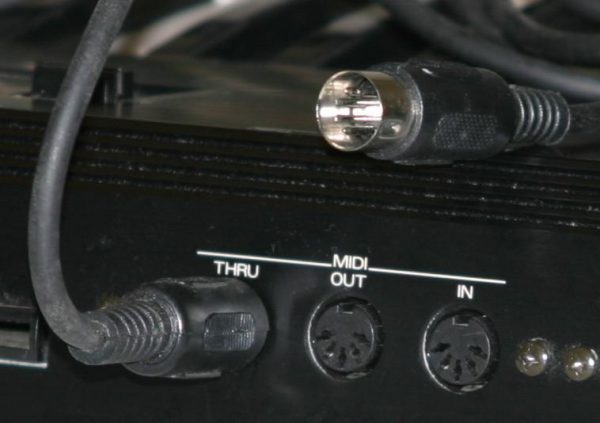
While serial communication between MCUs or between the MCU and a Nextion HMI happens at fixed voltage levels, either 3.3V or 5V, depending on the hardware, MIDI devices use a different approach: They work with 5mA current loops, which makes the communication more immune against noise which can be an issue on stage, where many keyboards, controllers, synths, and amps work on a relatively small space. Another advantage is the independence of the supply voltage: Maybe your keyboard works with 9V CMOS logic, but your synthesizer with 12V. You don’t even have to think about that, their internal MIDI interfaces make sure that 5mA, not more, not less, will flow. To avoid confusion and holy smoke caused by wrong plugging, MIDI interfaces use 5pin DIN sockets and the pins are used in a way that (almost) no harm can be done, even when accidentally an output to an output odd an input to an input.
But the biggest advantage is the avoidance of ground loops (which add hum and noise to the signal) by galvanic isolation. That means that each receiver side is equipped with an optocoupler. You see, it’s not trivial. A very simple 5V logic level to MIDI (and vice versa) interface designed by my friend Paul Stoffregen from pjrc.com looks like this:
While it does basically what it is designed for, it can’t be used as is with our Nextion HMIs. Remember, the Basic, Discovery, and Enhanced series have 3.3V logic, where the RX input is 5V tolerant. The Intelligent series use 5V logic. For both series, the output current of the TX pin is specified as 1mA, not enough to drive a 5mA current loop through only 2 resistors as in the schematic above. That means that for our purposes, the TX -> MIDI OUT side will need an additional level translator and driver to deal with the different voltages and to care about current amplification.
Another point is RF noise. That wasn’t an issue in the early 1980s when MIDI started, but nowadays, there are wireless devices and switches mode power supplies everywhere, and they pollute greatly the environment with unwanted RF radiation. Thus, some additional filtering and buffering won’t harm.
Teaser: To save you the headache of designing a Nextion specific MIDI interface, my colleagues in Shenzen/China and I are already working on it! There is some time left until it will come to market, so, there is enough time to learn about the MIDI protocol and its implementation in Nextion language!
The MIDI protocol
To deal with whatever protocol, the receiver has to know what to expect. The default Nextion protocol makes it relatively easy: Send a command in ASCII code, then send the terminator, 3 times 0xFF. As soon as the terminator is received, everything received previously, for example “t0.txt=\”hello world\””, will be parsed, interpreted, and then the command executed or an error code returned. The return from the Nextion is then different: The first byte tells us the nature of the message. Depending on the value, we’ll know if it’s an error or status message, or a data return. In ever case, with the exception of text data return, we’ll know from the first byte how many further bytes to expect, for example none for status and error codes, 4 for integer data return, etc.
MIDI has much in common with Nextion return codes since from the first byte, you’ll already know how many bytes to expect, most times 1 or 2. By this simple trick, it eliminates even the need of a terminator, except for the rare SysEx messages which can be longer. To make this protocol still more fail safe, the first byte has always its MSB set to 1, so that the values are between 128 and 255. Such a byte is always a command byte (sometimes called MIDI status byte). It ill then be followed in most cases by one or two data bytes whose MSB is always 0, so that these have always values between 0 and 127.
The anatomy of a MIDI command (or status) byte in general
Let’s divide this byte into the upper four bits and the lower 4 bits. Since the MSB is always 1, the upper half-byte can thus take 8 values between 8 and F (hex) or between 8 and 15 (dec). This value decides about the nature of the command. If it’s 8, 9, A, B, or E (hex), it’s a command which will be followed by 2 bytes, and if it’s C or D (hex), 1 byte will follow. In both cases, for all commands from 8n to En (hex), the lower half-byte, n, indicates the MIDI channel (by convention named 1 to 16) to which this command applies. Since n can take values from 0 to F (hex), we’ll have to add 1 to identify the channel.
Notes on and off and more…
0x9n tells the device to play a note (Note On) on channel n. The first data byte afterwards indicates the note to play and the second the velocity (how hard the key was hit).
0x8n tells the device to stop playing a note (Note Off) on channel n. The first data byte afterwards indicates the note to stop and the second the velocity (how quickly the key was released). Another way to stop a note is to send again a Note ON command for the same channel and the same note, but with the velocity byte = 0. This allows to save bytes when using the so called running state (see below).
0xAn tells the device what happened for a specific note after the note was started with its initial velocity (Aftertouch), for example with how much pressure a key is held. The first data byte indicates again the note, and the second the amount of pressure.
0xBn sets a controller value for channel n. This is specifically interesting for us, since this allows to de-materialize knobs, pedals, wheels and so on (we can add these to our Nextion GUI)! The first data byte indicates the controller number and the second the corresponding set value.
0xCn causes a program change on channel n. It is most times used to select a different instrument sound or timbre. The single following data byte contains the instrument (or program) number.
0xDn is somewhat outdated. Nowadays, with modern dynamic keyboards, one gets individual aftertouch pressure for each key (0xA0), no need for a channel-wide setting which applied to all notes. The first and only data byte contains the pressure intensity.
0xEn allows to bend the pitch of all notes of channel n. To allow smooth sliding off key, it uses 14 bits, packed into the 2 following data bytes @7 bits.
Sytem Exclusive (SysEx) messages
Now, there are still the Fm command bytes… The lower half byte m indicates not longer the MIDI channel, but the command subtype: If m is 0 (0xF0), that indicates that the following data bytes, independent of their number, are a manufacturer specific system message of variable length. A terminator (0xF7) indicates the end of the message. Some manufacturers do not respect the requirement of this terminator byte. That’s why we should consider a SysEx message as “done” when any other command byte arrives, with the exception of System Realtime messages (0xF8 to 0xFF, see below) which have to be handled, as the name says, in real time, while the SysEx data flow may continue. If m is 1, 2, 3, or 6, these allow a master midi device to control a slave for example by having the latter playing specific music sequences. Seldom used, we’ll look into details when we start coding our own MIDI parser.
System Realtime messages
These allow two MIDI devices to remain synchronized when playing together. 0xF8 is the MIDI clock. When used, it has to occur 24 times during a quarter note. 0xFA forces the slave to start the selected sequence at this very moment. 0xFB asks the slave to resume the sequence, and 0xFC stops playing the current sequence. Finally 0xFE is a kind of watchdog. If sent once, it has to be repeated every 300ms to keep the device “alive”, if not, it will stop everything. Also seldom used.
Reducing latency by saving bytes: Running state
Imagine, you play a C major chord on your keyboard without hitting the keys too hard (default velocity). The generated MIDI messages are 90 3C 40 (start middle C), 90 40 40 (add the E above), 90 43 40 (add the G), and 90 48 40 (add the upper C). 4 notes = 12 bytes. At 31250 baud, the transmission takes 4ms and the notes will start one after the other each with 1ms delay after the previous one. Running state allows to reduce this delay: As long as the command byte (here 0x90) remains the same, no need to re-send it each time! After the first “full” message (90 3C 40), all following messages can omit the command byte as long as it remains the same and send only the corresponding data bytes. Thus, our command sequence shortens to 90 3C 40 40 40 43 40 48 40. From 12 down to 9 bytes, 1ms saved, and the delay between notes reduced from 1ms to 0.7ms. Running state can be applied for all voice commands from 0x8n to 0xEn. It does not apply to system commands which start with 0xFm.
Now that we know our protocol with all details, we might finally start coding next week and see what a Nextion HMI can do in MIDI practice.
Happy nextioning – see you next week!


