The Sunday Blog: Nextion GPIO
Part2: Digital Output and PWM step by step
First of all, thank you so much to all who have partaken in the 2022 survey, up to now! Those who haven’t yet may do so here. The idea is for us to know better what our readers do with their Nextion HMIs and what they are interested in. Some of the replies I read were a huge surprise for me. The smaller (4.3″ and 5″) Intelligent P series are obviously more widespread than I thought. You may thus expect more example projects for these devices over the next year!
Now, let’s come to today’s topic: Mentioned as a point of interest by more than 30% of the survey replies, it’s thus the first of the “you asked for it” chapters. Since I drew already first parallel lines between Nextion and Arduino GPIO in this article last November, I owed you this follow-up which makes the jump from theory to practice, anyway.
The digital outputs
The Nextion Enhanced K series and Intelligent P series HMIs have 8 GPIO pins IO0 to I07. These are accessible, together with 5V power and GND on a 10pin flat ribbon cable connector on the back side of the HMI. For those who feel uncomfortable with this, a small and simple IO adapter board 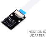 is available which comes with a 10cm flat ribbon cable and allows direct soldering of your IO connections or using standard 2 x 5 pin headers with a 1/10″ raster. 2 or 4 of the IO pins are even PWM capable (IO4 to IO7 for the K series, IO6 and IO7 for the P series), but we’ll look into that later, below.
We’ll use a RGB LED with a common cathode and three distinct anode pins on a breakout module which contains already the required current limiting resistors. I had still this one in the drawer, but a similar model will do it, too. Thus, we connect the GND pin of the LED module with the GND of the Nextion IO adapter, the R pin with IO5, the G pin with IO6 and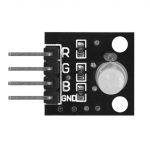 the B pin with IO7. That’s it for the hardware, no soldering required 😉 !
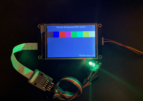
Now, having 3 digital pins which can have a state of 0 (off) or 1 (on) should allow us to generate and visualize 2 ^ 3 = 8 states which our RGB LED would show as 8 different colors from black (all 3 off) to white (all 3 on). Then, there are 3 variants where only one of the 3 would be active and thus result in red, green, or blue light, and 3 where always 2 of the 3 would be active, resulting in magenta (blue+red), cyan (blue+green) and yellow (red+green).
And that’s what the first page (page 0) of today’s demo project is about. A page with a static title text, 8 text components (using less memory than buttons) without text but with the corresponding background colors. Clicking on a specific color will make the RGB light up in the same color. In the page preInitialize event, we reset the three corresponding system variables IO5 to IO7 first to prevent uninitialized chaos before we use the cfgpio function to configure pins 5 to 7 as push-pull outputs with no event binding (the third parameter is thus null, we’ll look at this in a different article, later):
// reset gpio variables
pio5=0
pio6=0
pio7=0
// configure IO pins as push-pull outputs:
cfgpio 5,2,0
cfgpio 6,2,0
cfgpio 7,2,0
No black magic and no rocket science, here! The TouchPress event code behind the 8 text boxes is simple, too. Lets take the example of t6, the cyan one:
pio5=0
pio6=1
pio7=1
We see that R is switched off, and G and B are switched on. For the others, it’s similar, only the zeros and ones change, depending on the desired color.
Finally, in the bottom right corner, a text box as another memory saving pseudo button allows us to change to page 1 by clicking on it.
Use PWM to get more sophisticated results
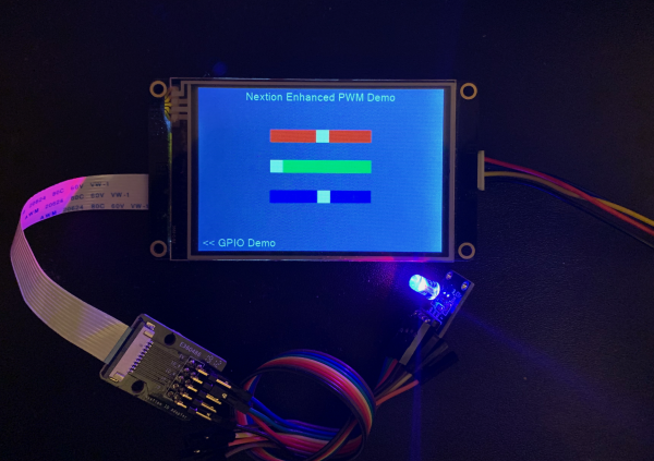
While the previous example allowed us to switch the single color components R, G, and B simply on and off, PWM allows us much finer, almost analog graduation. This is simply done by writing a value between 0 and 100 to the corresponding system variables. With 3 of these for the 3 color components, we are theoretically able to generate 101 ^ 3 = 1 030 301 different colors, but neither the nonlinear control curve of the LEDs nor the sensitivity of the human eye allows us to distinguish all these. But there remains still a huge amount of color shades to play with. As before, in the page’s preInitialize event, we reset the variables and configure the pins, this time with the second parameter = 3 which switches them into PWM mode:
// reset pwm variables
pwm5=0
pwm6=0
pwm7=0
// configure IO pins as PWM outputs:
cfgpio 5,3,0
cfgpio 6,3,0
cfgpio 7,3,0
Now, on the page, we have 3 sliders whose .val attribute goes from 0 to 100. Thus, it’s simple to set the corresponding ppm variable to the slider’s value with a one liner. pwm5=h0.val for red, pwm6=h1.val for green, and pwm7=h2.val for blue. I put these lines always twice, once in the touchMove event, so that one can already see the effect while moving the slider and once in the touchRelease event to make sure that the pwm value corresponds always to the (last) displayed slider position. Again, no rocket science.
Here is the HMI file to play with: gpioDemo.HMI
Have fun, and don’t forget to fill in the aforementioned survey form.
Happy nextioning!


