The Sunday Blog: Advanced programming techniques
Nextion HMI as a serial monitor (1)
Normally, I design my projects first on paper with a pencil until I have an overview over the required specifications, before I finally order the materials accordingly, a powerful enough MCU and a Nextion HMI with the needed size and resolution. But this Easter weekend, I sat there and thought about the Nextion 4.3″ Standard HMI which I have had in a drawer for a very long time. And I thought for myself: “After all, developing and debugging Nextion based projects need sometimes a few extra tools. But I’m not always comfortable with going through all drawers to find the TTL-to-USB adapter, launching the Windows Computer which I use rarely, since besides Nextion development, I’m a Mac addict, launching the Nextion Editor, load the project, launch the Simulator, establish a serial connection, and, and, and…” Finally, I found that having a separate serial monitor on the bench to visualize either data sent out by the MCU towards the Nextion or by the Nextion towards the MCU would be a nice thing.
At the same time, a new blog article should be published, so I decided to combine this with a “lesson” about a seldom mentioned advanced Nextion functionality: Protocol reparsing, which is available on all series, Standard, Enhanced, and Intelligent and which allows to circumvent the firmware and to take the control over the incoming data stream.
What is “protocol reparsing”?
To explain this, we have to understand first that each Nextion HMI has a 1024 bytes sized serial input buffer. Everything which arrives over the RX line goes there. In its default operation mode, the Nextion firmware will analyze (or parse) the buffer’s content and react accordingly: If it recognizes a valid command, it will execute it. If not, it will, depending on the setting of the bkcmd value, send an error message back. In ever case, the processed bytes will be removed from the buffer to free up space for new input data.
All this is controlled by another system variable, recmod, which is 0 by default. As soon as we set it to 1, the firmware will stop parsing and processing the content of the buffer and our code should immediately take over to prevent a buffer overflow. This can be done with very few things in mind: First, there is the usize variable: It tells us how many unprocessed bytes are waiting in the buffer. Second, there is the udelete command which takes an integer as a parameter and which allows to remove the corresponding number of bytes from the beginning of the buffer (the oldest ones). Each single byte in the buffer can be directly read by using the u[] array: u[0] gives us the very first and u[1023] the very last byte in the buffer.
It’s now fully up to us to use all this for our project.
The project
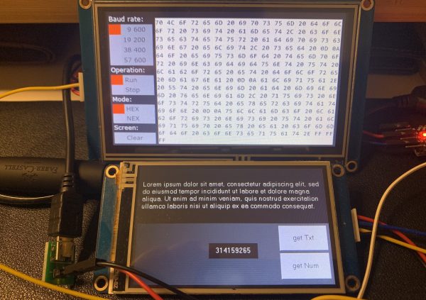
In this first part, we will accomplish the simpler thing: Just reading the incoming bytes and output these as human readable HEX codes, nicely formatted (see picture above) in a huge text component which can hold 16 lines with 16 bytes each. The tricky things here are the formatting, spaces and breaks at line level, and scrolling by discarding always the first line when a 16th is begun at component level. Details will follow below.
In the second part, next weekend or so, we’ll extend the project to analyze and decode Nextion return codes, so that one Nextion HMI can serve as a debugger for the other.
The GUI
To save valuable RAM, I decided to minimize the number of components on the page and to put whatever made sense into a static background picture. This allows to use sliders to select between pre-defined values in the Baud rate, Operation and Mode menus. And since I was already drawing the background this way, I also added the Screen:Clear thing to the background, so that a simple and invisible hotspot will be enough to transform it into a button.
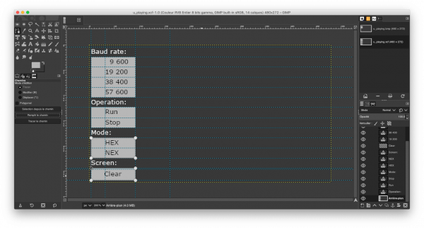
Exporting this as a RGB565 bmp, importing this as the page0 background in the Nextion Editor, positioning the hotspot component over the Clear button and adding the three sliders vertically on the left side of the Baud rate, Operation, and Mode selector areas, was quickly done.
Then, I thought about formatting the incoming data stream with the handling of spaces, line breaks, scrolling, and so on, and I decided for a two-step approach: On the right side of the screen, there are two text components: The first at the bottom is only one line high and will allow to assemble up to 16 bytes with the spaces in-between. Once it is “full”, it will be added to the bottom of the upper, 15 lines high text component. If there were already 15 full lines, the top one would be deleted. The advantage is that up to 16 incoming bytes can be processed without caring about scrolling which should increase the execution speed.

Definitions in program.s
Just two variables, spl as a counter for the number of bytes in the current line, and tmp for temporary purpose, before we jump to page 0.
int spl=0
int tmp
page 0                       //Power on start page 0
The page PostInitialize code
There is not much inside: Depending on the actual baud rate, the slider h0’s value is set accordingly. If the actual baud rate does not correspond to any of the 4 available values, 9600 baud will be set as a forced default.
if(baud==9600)
{
  h0.val=3
}else if(baud==19200)
{
  h0.val=2
}else if(baud==38400)
{
  h0.val=1
}else if(baud==57600)
{
  h0.val=0
}else
{
  h0.val=3
  baud=9600
}
The baud rate slider’s TouchRelease code
The code sets just the baud rate according to the slider’s value which goes from 0 to 4. The first line, h0.val=h0.val might look superfluous at a first glance, and yes, it is. It’s only there for esthetic reasons: The slider component is 80 pixels high, the slider knob 20. So, the slider can theoretically take 60 different positions. Some of these might visually be almost in the middle between two of the four desired positions. This line makes it just snap into the visually expected position.
h0.val=h0.val
if(h0.val==2)
{
  baud=19200
}else if(h0.val==1)
{
  baud=38400
}else if(h0.val==0)
{
  baud=57600
}else
{
  baud=9600
}
The operation slider’s TouchRelease code
It changes the recmod variable accordingly which means that in Run mode, recmod is 1 and our serial monitor will work, and in Stop mode, recmod is 0 and the Nextion firmware will process incoming commands and data as usual. Then, only after activating the Run mode, the serial buffer is cleared eliminate remains of the previous processing. Finally, the timer which will look at regular intervals if data is there and needs to be processed, is enabled.
h1.val=h1.val
recmod=h1.val
if(h1.val>0)
{
  udelete usize
}
tm0.en=h1.val
The mode slider
…is for the moment fixed in HEX mode, we’ll add the NEX mode next time.
The clear hotspot’s TouchPress code
… empties the text fields and clears the already processed bytes of the current line from the buffer before resetting the symbol counter:
t0.txt=""
t1.txt=""
tmp=spl+1
udelete tmp
spl=0
And finally the “magic sauce” which happens in the timer
The first line, doevents, allows the Nextion to react on user interaction and never to be blocked by processing. Our spl variable tells us how many bytes have already been read and converted into the current line, so that we need only to act if more bytes are waiting in the buffer. If that is the case (usize>spl), then we’ll take the next byte and convert it into a two-digit hexadecimal representation with covx. This intermediate result is stored in va0.txt and then appended to t0.txt. So far, so easy. Then, we’ll have to see if the line isn’t yet full (spl<15) in which case we append still a space character. But if it’s full, we have first to check if the huge text field above can still accept a line. For this, we use the btlen function which stores the number of bytes in t1.txt into the tmp variable. A single line consists of 2×16=32 bytes for the hexadecimal characters, plus 15 bytes for the spaces in-between, plus 2 bytes for the (invisible) new line code, which makes 49 bytes. 14 lines x 49 bytes makes 686 bytes. That’s why we check if (tmp>=686) which indicates us if more than 14 (of the 15) lines in t1.txt are taken. If that’s the case, we use the substr function to extract all the content of t1.txt without the first 49 bytes (the oldest line) and copy t back into t1.txt. So, we’ll have enough space to add the next full line, preceded by a new line code. After the content of t0 has been moved to t1, we empty t0, reset spl and delete the just processed 16 bytes (which have gone through va0 and t0 into t1) from the buffer. This is less resource consuming and quicker as deleting each single byte from the buffer after processing it.
doevents
while(usize>spl)
{
  covx u[spl],va0.txt,0,2
  t0.txt+=va0.txt
  if(spl<15)
  {
    t0.txt+=" "
    spl++
  }else
  {
    btlen t1.txt,tmp
    if(tmp>=686)
    {
      substr t1.txt,t1.txt,49,733
    }
    if(tmp>0)
    {
      t1.txt+="\r"
    }
    t1.txt+=t0.txt
    t0.txt=""
    spl=0
    udelete 16
  }
}
That’s it!
As usual, there is no need for you to copy/paste and draw everything again, you can download the full HMI here: u_playing.hmi
Testing
Remember the HMI project from last time which we used to send data and text from the Nextion to the MCU? You can re-use it now: blog_210321.HMI
Provide both Nextion HMI displays with +5V and a common ground, then connect the other Nextion’s TX with our Serial Monitor’s RX, switch the Operation slider from Stop to Run, then press the get Num and get Txt buttons of the other and be amazed by the result!


