The Sunday Blog: Talking to your Nextion HMI
Part 5: A digital volt meter DVM with Nextion HMI and Arduino Mega
In the last episode, we saw how the Arduino could basically send commands over to the Nextion, and we used that for displaying some funny animated texts. Before we move on, it will be needed to look critically back on our code and eliminate some “not so optimal” things. But we will end up with a simple digital volt meter today, and I guess it’s worth it.
Handling the timing in a better way
When take a closer look to the Arduino code from last week, we see that our Arduino was always occupied at 100%, either with sending commands over to the Nextion HMI or literally doing nothing but nothing by executing delay(). While this allowed to have the correct timing for our multiple text animations, we risk to run into serious issues in the future. The Arduino delay() function makes the MCU “hang” for the indicated number of milliseconds. And as you might know, this “hanging” doesn’t allow the Arduino to do other things in the meantime, such as for example listening to incoming data over serial. Even though this week’s project won’t yet use any return communication from the Nextion HMI to the Arduino, we’ll better be prepared.
To keep things simple and easily understandable, we will neither write strange HEX numbers into the Arduino hardware timer registers and redirect interrupt vectors, nor will we use a timer library, as long as we can solve our problem with on-board resources. One of these helper tools is the Arduino millis() function. It simply counts the milliseconds since booting or reset in an unsigned 32bit variable. That has the advantage that it will only roll over after more than 4 billions of milliseconds which is roughly 50 days. More than enough for handling our timing.
How can we use the millis() function for our purpose? Let’s take another unsigned 32bit variable, call it “timTarget” and initialize it to 0 at the beginning. Then, at each loop pass, check if millis() is greater or equal than timTarget. If yes, define a new time Target by setting timTarget to the current millis() value PLUS the required delay in milliseconds before executing your timed task. If no, do nothing, or check incoming serial data, or check the mail, or get a coffee, or whatsoever.
A symbolic code example might look like this:
// Global variables
uint32_t timTarget = 0;
uint16_t interval = 200 ; // run the timed task 5 times per second, each 200ms

void loop() {
  if(millis() >= timTarget) { // time is over, let's do what is needed
    timTarget = millis() + interval; // Set the next time target
    // code executing the timed task
  }
  else { // time is not yet over, let's do other stuff
    // code executing other tasks
  }
}
Using that improved time handling
With this and the code we wrote last week, we have already done most of the required coding for our digital volt meter. With this, we can now do an analogRead(A0) every 200ms. Depending on the voltage on pin A0, we’ll get a value from 0 (corresponding to 0V) to 1023 (corresponding to the maximum voltage which is 5V) in steps which correspond to 0.0049 V each. To display the corresponding voltage, we will use an xfloat component in the Nextion GUI (see next paragraph) with 1 digit left of the decimal point and three digits right of the decimal point. That has the advantage that we can send the voltage in millivolts as an integer over to the Nextion, and the xfloat will automatically add the decimal point to display the value in Volts. The integer to display must be computed from the value returned by analogRead(A0): dispVal = readVal * 5000 / 1023; – this way, it’s quicker and more precise than the Arduino map() function.
Now, let’s just think about serial communication economics. Imagine, we get 5 samples per second from analogRead() with our timed code, thus, we would also update our display 5 times a second, even if the value which we want to display hasn’t changed in a time. Not smart. Let’s better use another variable which keeps the last displayed value and send only data to the Nextion when the currently calculated display value is different from the last one. So, we can use the following code block in our loop, at the place of “// code executing the timed task”:
  readVal = analogRead(A0);
  dispVal = readVal * 5000 / 1023;
  if(dispVal != lastVal) {
    sendCmd("x0.val=" + (String)dispVal);
    lastVal = dispVal;
  }
Assembling the full Arduino code
We will not reinvent the wheel. We re-use the #defines, the sendCmd() function and the setup() code from last week. We add the required global variable definitions. We take the timed loop() and the core code block from above. That’s it :
#define nexSer Serial1 // Controlling the Nextion HMI using Serial1 (pin18 of the Arduino Mega) to prevent interfering with code upload
#define dbgSer Serial // Debug using default Serial over USB towards Arduino Serial Monitor
#define DEBUG // Comment this out if you don't need to see what happens in the Serial Monitor

// Global variables
uint32_t timTarget = 0;
uint16_t interval = 200 ;
uint32_t readVal = 0;
int32_t dispVal = 0;
int32_t lastVal = 0;

void sendCmd(String cmd)
{
  nexSer.print(cmd);
  nexSer.write("\xFF\xFF\xFF");
#ifdef DEBUG
  if(cmd.length() > 0)
  {
    dbgSer.print("Sending command : ");
    dbgSer.println(cmd);
  } else
  {
    dbgSer.println("Empty command issued to clear the buffer");
  }
#endif
}

void setup() {
  dbgSer.begin(9600);
  while(!dbgSer); // Wait for connect
  nexSer.begin(9600);
  while(!nexSer); // wait for connect
  sendCmd(""); // clear the buffer
}

void loop() {
  if(millis() >= timTarget) {
    timTarget = millis() + interval;
    readVal = analogRead(A0);
    dispVal = readVal * 5000 / 1023;
    if(dispVal != lastVal) {
      sendCmd("x0.val=" + (String)dispVal);
      lastVal = dispVal;
    }
  }
  else {
    // Do some other stuff if needed
  }
}
If you don’t want to type or copy/paste all that in your Arduino IDE, you may download the .ino file here: sketch_nov29a_dvm.ino
The hardware setup
Connecting the Nextion HMI to the Arduino Mega is the same as last week :
- Nextion GND (black) => Arduino Mega GND
- Nextion +5V (red) => Arduino Mega 5V
- Nextion RX (yellow) => Arduino Mega TX1 (pin 18)
Using the integrated ADC of the Mega limits the input voltage range of our DVM to the 0 – +5V range without further hardware like buffers, voltage dividers, etc. For testing purposes, we will simply connect a potentiometer which will allow us to set arbitrary voltage values within that range. It needs to be connected like this:
- Potentiometer cold (left) pin => Arduino Mega GND
- Potentiometer wiper (center) pin => Arduino Mega A0
- Potentiometer hot (right) pin => Arduino Mega AREF
Now, we are almost done. Arduino code – check! Wiring – check! But, hold on, we need still one more thing…
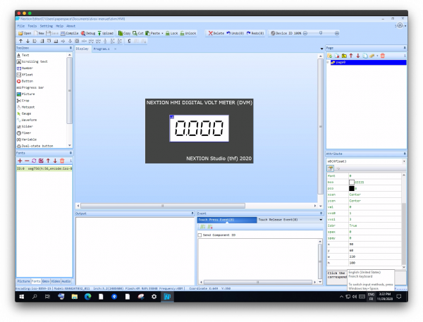
The GUI for our Nextion HMI DVM
In the Nextion Editor, we start a new project, call it dvm.hmi, provide the start page with either a solid color background, or a background picture with some static text, as I did. It is good practice to integrate all static GUI elements into a page background picture to reduce the number of GUI components and thus to save RAM and increase the execution speed on the Nextion side. Then, we place a single xfloat component centered on the page, adjust the number of decimals right and left of the decimal point, create and/import a nice LCD font and we are done. It’s not rocket science.
… or download the ready-to-use .hmi file here: dvm.HMI
Compile and upload it to your Nextion HMI, turn the potentiometer, and have fun!


