The Sunday Blog: Understanding and Customizing HMI components
Part 2: A project without visible components
First of all: Did you read about the NEXTION Summer Contest where you can win a NEXTION HMI display and a Foca Max adapter?
After we had looked into some basics of touch GUI technology and NEXTION’s advantages over proprietary solutions, last week, and we made acquaintance with the most elementary and simple hotspot component, it’s time to move on. Most other components inherit from the hotspot since they have the same attributes (plus more specific ones in addition) and they have identical Touch Press and Touch Release events and the corresponding Send Component ID functionality. Out of that, the hotspot gives us another huge advantage for optimizing our Nextion code, but we will look into that in a further episode.
A component which isn’t a component
Automatically present at least once in every project, the page acts as a container for all other components on the current screen, but when we look at its attribute list, we find exactly the same attributes as we find for the hotspot. Just the height(h) and width(w) attributes are immutable and correspond always to the screen height and width. In addition, we find a dynamic attribute set for the visual aspects. Everything depends on the sta style attribute which can take three values: no background, solid color, or image. Depending on our choice, a second attribute will show up: bco for the background color when you opted for solid color, or pic for the picture resource when you selected image for sta.
Now, imagine that you need to know where your screen has been touched when a Touch Press events happens on the page. One might naturally place different components on the page to detect touch events in different zones, but sometimes it might be more efficient to use the tch0 and tch1 system variables to know the region where the screen has been touched, and thus to reduce the number of components on the screen.
What is the advantage of reducing the number of components?
First, reducing the number of components saves RAM because every component and each of its attributes needs RAM to hold actual values when the containing page is displayed. Second, reduce the number of places where you have to write and maintain event code. Following the old developer principle called KISS (keep it simple and safe), reducing system resource usage and keeping the code compact in a few places, you’ll get still more out of your project!
The project almost without components
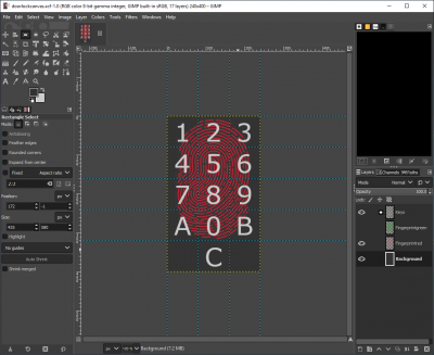
As you have perhaps seen in this blog’s featured image, we’ll build a numeric door locker as you can find them on garages, hotel rooms, and so on. It features keys from 0 to 9, A and B, plus a C key to clear the last entry. Typically the unlock sequence has 4 numbers followed by one of the letters, A or B, for example 2718A.
How can this be done with (almost) no components? It’s simple. We “pack” all visual elements in the page background image. This can be done in most graphic programs. I personally use the free and open source Gimp 2.10 since it allows the use of guide lines and of different layers so that creating even different variants of the same picture is pretty straightforward by hiding or showing different layers before exporting the corresponding bmp. I wanted the decorative fingerprint in the background to change from red to green when the correct unlock code was entered. Thus I imported the fingerprint twice into different layers, the first time in red and the second time in… red, before I changed it to green. On a top layer, I placed the different numbers and letters, after having divided the image into 15 equal 80x80px zones. Then I exported the first picture with the red fingerprint visible and the green one hidden. Afterwards I did the same with the red one hidden and the green visible. This gave me the two alternative background bmp files to import in the Nextion editor with a minimal effort:
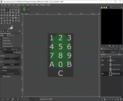
With these two background images imported as picture resources into the Nextion editor, selecting the page’s sta attribute to image and the pic attribute to 0, all visual design tasks are done. The rest is just thoughtful coding:
We need three numeric variables which we declare in the program.s file of the project for the sake of simplicity. The first 2, row and col, will hold the calculated row (0 to 4) and col (0 to 2). The last, position, will hold the value of 3 x row + col, so that we’ll have a value from 0 to 14 for the 15 possible key press positions. That was the numeric part which represents the first 3 lines of the page’s Touch press event code.
Now, going from numeric to alphanumeric
In the next step, we’ll need to translate our position code which goes from 0 to 14 into the corresponding alphanumeric value. And that’s where we need another component type, the variable to hold a few strings, since program.s does not (yet) allow to declare string variables. Thus, we add a first variable, change its STA attribute to String, set the txt_maxl to 15 and set the txt to 123456789A0B+C+. The substr function will now allow us to extract the corresponding character into another string variable, called lastS, which needs only a txt_maxl of 1. That’s the fourth line of our event code.
Now, we have to decide what should happen, depending on which virtual key was pressed. If the position variable is < 12 which means that any of the 0 to 9, A, or B key has been pressed, we append the charcater in lastS to our third String variable, called buffer, which was initially empty and has a txt_maxl of 5. In addition, but only if position is 9 or 11 which corresponds to the A and B keys, we’ll check if the string in buffer is equal to the string in our fourth and last String variable called secret and which was initialized with our unlock code 2718A in the txt attribute (and a txt_maxl of 5). If both match, we should react accordingly and open the door after switching the page’s pic attribute from 0 to 1 to turn the fingerprint green. In our example, we send the string “OPEN” followed by a new line character over Serial, but that might be adapted to different needs. With an enhanced series HMI, one could for example use GPIO and a MOSFET transistor to enable the door unlock solenoid directly. If the strings don’t match, we’ll set the page’s pic attribute to 0, so that the fingerprint will be red, and send “ERROR+LOCK” over Serial. As a protection against brute force attacks, the buffer will not be cleared after a wrong entry, thus additional key presses will not find their way into the buffer whose max length is 5. A press on C is always requested to clean the buffer before one does the next attempt.
Finally, we code what will happen if the position value is 13 which means that the C key has been pressed: We turn the fingerprint red, we clear the buffer variable and we send “CLEAR+LOCK” over Serial. That’s all and we are done in just 26 lines of code which includes the lines containing only brackets or comments.
How to visualize the Serial return from the HMI
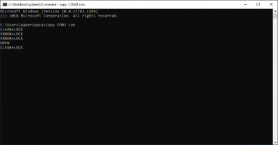
No, we don’t need serial monitor software. After connecting our HMI via the Foca Max or any other FTDI or CP2102 based UART TTL to USB adapter to our computer, we look up in the device manager which COM port has been attributed by Windows’ USB enumerator. In my case, it is COM3. Now, we need to open a command prompt window by using the Win+R key combination, and enter cmd and click on OK. In the command prompt window, we enter copy COM3 con, followed by Enter. Now, all HMI output will be shown on the screen. When you are done, just press ctrl+C to return to the normal command mode. In the following screen, I pressed the C key first, then I tried entering two wrong codes, before I entered the correct code, 2718A and finally pressed again C to clear and lock:
As usual, you may download the complete HMI file in the NEXTION Forums to experiment with the code and to modify or extend it. Happy unlocking!


